Technical Appendix
6.2 PLC user interface signals
6-116
SINUMERIK 802C
6FC5 597–3AA20–0BP2 (01.02)
390x1001
(axis)
390x1002 Lubrica-
(axis)
tion pulse
390x1003
(axis)
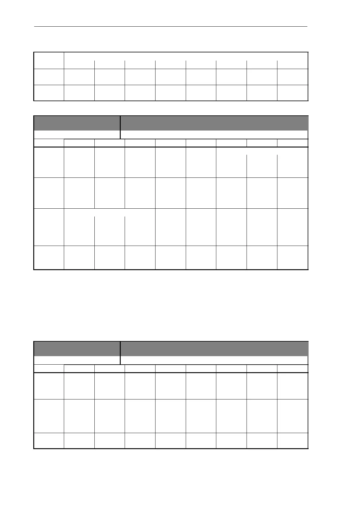
Signals from spindle
3903 Signals from spindle [r]
Data block
Interface NCK –––––> PLC
Byte Bit 7 Bit 6 Bit 5 Bit 4 Bit 3 Bit 2 Bit 1 Bit 0
Set gear stage
39032000 Change
gear
(spindle)
C B A
Actual di-
rection
Spindle Set Set Speed
39032001 of rotation within set speed speed limit
(spindle)
CW range increased limited exceeded
Active spindle mode Tapping
39032002 Control Recipro-
cating
Position-
ing
without
compen-
sating
(spindle)
mode mode mode chuck
39032003
(spindle)
6.2.6 Signals from/to MMC
Program control signals from MMC (retentive area)
(see also signals to channel V32000000)
1700 MMC signals [r]
Data block
Interface MMC –––––> PLC
DBB Bit 7 Bit 6 Bit 5 Bit 4 Bit 3 Bit 2 Bit 1 Bit 0
Dry run
17000000 feed M01
(MMC –––>
PLC)
selected selected
Program Feed
17000001
test
selected
override
for rapid
(MMC ––>
PLC)
traverse
selected
Select
17000002 Skip

 Loading...


