Installing the Control System
2.3 Connecting the individual components
2-29
SINUMERIK 802C
6FC5 597–3AA20–0BP2 (01.02)
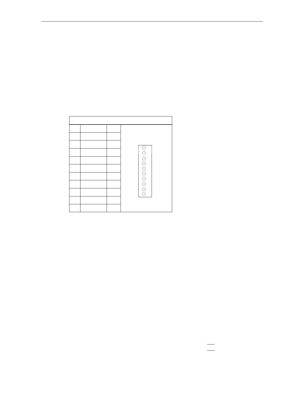
2.3.5 Connecting handwheels (X10)
Pin assignment of the connector on the ENC side
Handwheel interface
Connector designation: X10
MPG
Connector type: 10–pin mini-Combicon plug connector
Table 2-12 Pin assignment of connector
X10
X10
Pin Name Type
1 A1 I
2 A1_N I
3 B1 I
1
4 B1_N I
5 P5_MS VO
6 M5_MS VO
7 A2 I
8 A2_N I 10
9 B2 I
10 B2_N I
Signal names
A1, A1_N Track A, true and negated (handwheel 1)
B1, B1_N Track B, true and negated (handwheel 1)
A2, A2_N Track A, true and negated (handwheel 2)
B2, B2_N Track B, true and negated (handwheel 2)
P5_MS 5.2 V supply voltage for handwheels
M Supply ground
Signal level
RS422
Signal type
VO Voltage output
I Input (5 V signal)
Handwheels
Two electronic handwheels can be connected which must meet the following requirements:
Transmission method: 5 V square–wave (TTL level or RS422)
Signals: Track A as true and negated signal (U
a1
, U
a1
)
Track B as true and negated signal (U
a2
, U
a2
)

 Loading...


