Installing the Control System
2.3 Connecting the individual components
2-28
SINUMERIK 802C
6FC5 597–3AA20–0BP2 (01.02)
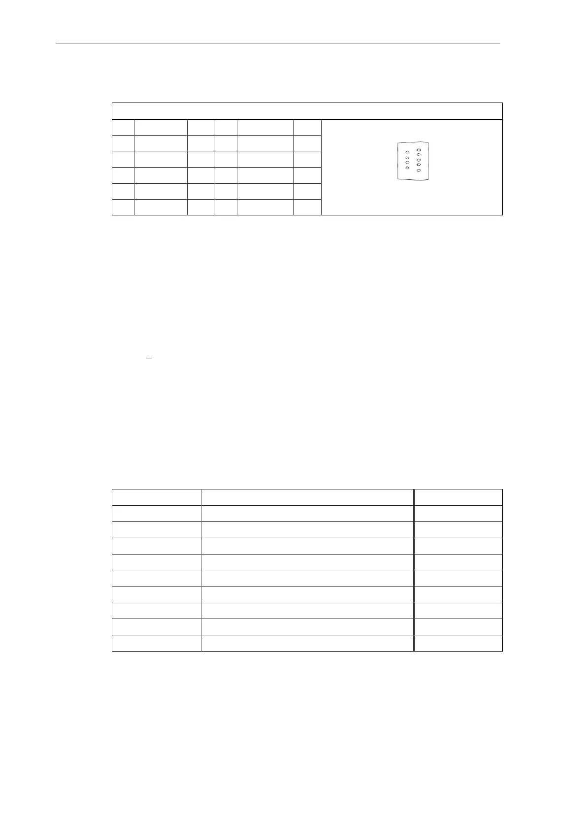
Table 2-10 Pin assignment of connector X2
X8
Pin Name Type Pin Name Type
1 6 DSR I
2 RxD I 7 RTS O
1
6
3 TxD O 8 CTS I
5
9
4 DTR O 9
5 M VO
Signal description:
RxD Receive data
TxD Send data
RTS Request to send
CTS Send enable
DTR Standby output
DSR Standby input
M Ground
Signal level
RS232 (+ 12 V)
Signal type
I Input
O Output
VO Voltage output
Cable for WinPCIN
Table 2-11 Cable for WinPCIN: Pin assignment of the Sub–D connector
9–Pin
Name 25–Pin
1 Shield 1
2 RxD 2
3 TxD 3
4 DTR 6
5 M 7
6 DSR 20
7 RTS 5
8 CTS 4
9

 Loading...


