Installing the Control System
2.3 Connecting the individual components
2-27
SINUMERIK 802C
6FC5 597–3AA20–0BP2 (01.02)
Connectable encoder types
Incremental 5 V encoders can be connected directly.
Characteristics
The encoders must meet the following requirements:
Transmission method: Differential transmission with 5 V square–wave
signalsOutput signals:
Track A as true and negated signal (U
a1
, U
a1
)
Track B as true and negated signal (U
a2
, U
a2
)
Zero signal N as true and negated signal
(U
a0
, U
a0
)
Max. output frequency: 1.5 MHz
Phase offset between
tracks A and B: 90° "30°
Current consumption: max. 300 mA
Cable lengths
The maximum cable length depends on the specifications of the encoder power supply and on
the transmission frequency.
To provide fault–free operation, make sure that the following values are not exceeded when
using preassembled interconnecting cables from SIEMENS:
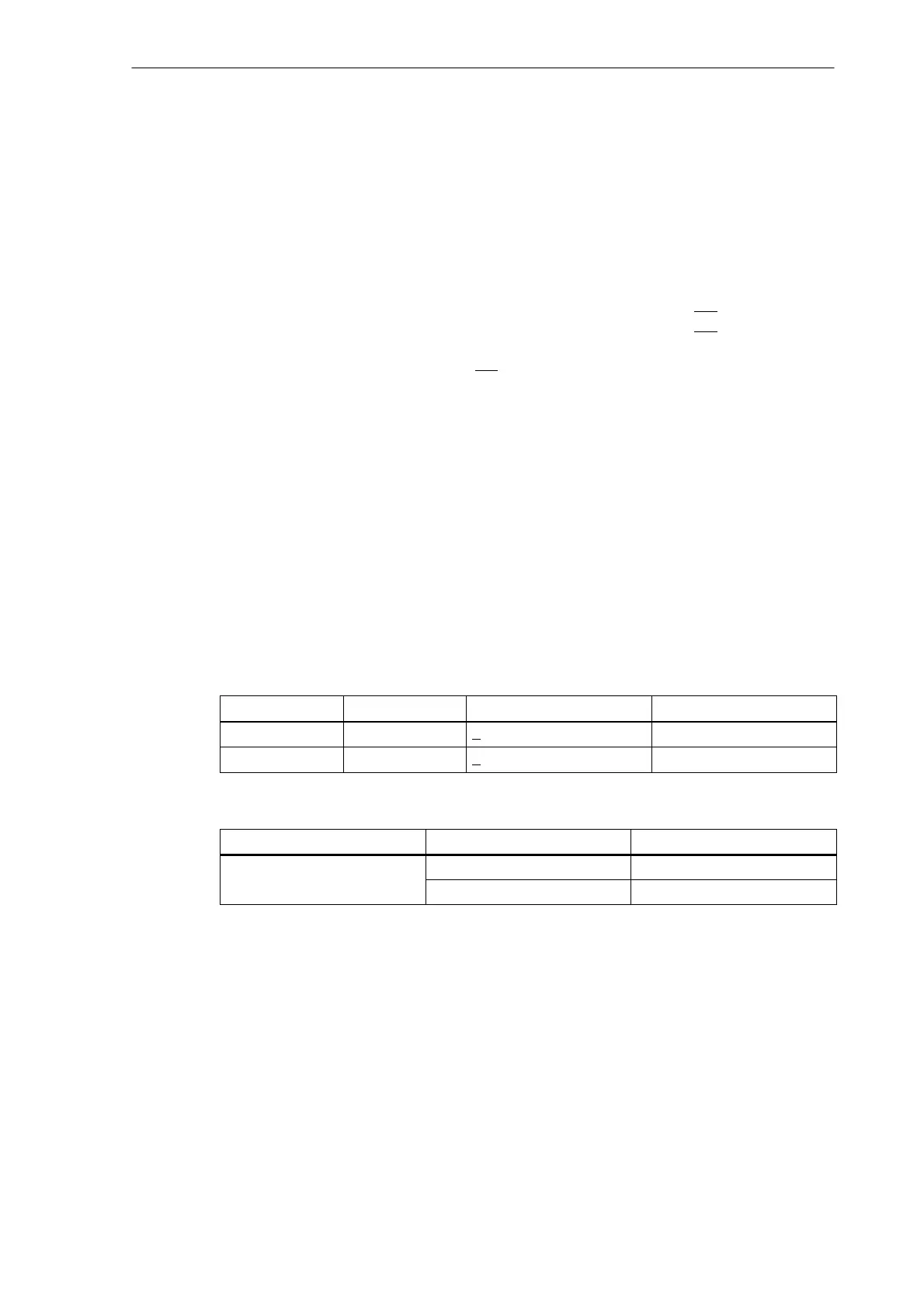
Table 2-8 Maximum cable lengths depending on the encoder power supply
Supply Voltage
Tolerance Current Consumption Max. Cable Length
5 V DC 4.75 V...5.25 V < 300 mA 25 m
5 V DC 4.75 V...5.25 V < 220 mA 35 m
Table 2-9 Maximum cable lengths depending on the transmission frequency
Encoder Type
Frequency Max. Cable Length
1 MHz 10 m
incremental
500 kHz 35 m
2.3.4 Configuration of the RS232 interface connection (X8)
Pin assignment of the connector on the ENC side
RS232 interface
Connector designation: X2
RS232
Connector type: 9–pin sub–D plug connector

 Loading...


