Installing the Control System
2.3 Connecting the individual components
2-25
SINUMERIK 802C
6FC5 597–3AA20–0BP2 (01.02)
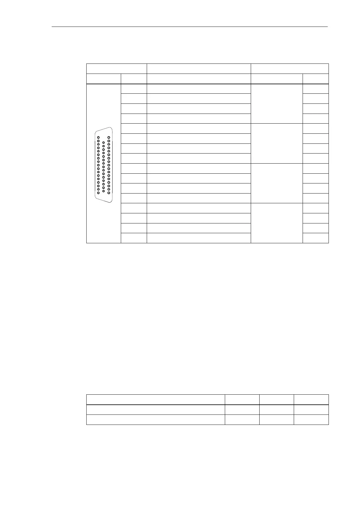
Table 2-4 Cable assignment (for type 6FX2 002–3AD01)
NC Side
Cable Drive Side
PIN Core Color Signal Name PIN
14 black 1st axis 1.9
47 brown 1.65
34 red 1.4
1 orange 1.56
15 yellow 2nd axis 2.9
1
18
34
48 green 2.65
2 blue 2.14
35 purple 2.56
16 gray 3rd axis 3.9
49 pink 3.65
36 white/black 3.14
17
33
50
3 white/brown 3.56
17 white/red Spindle 4.9
50 white/orange 4.65
4 white/yellow 4.14
37 white/green 4.56
Drives with analog interface Signals
One voltage and one enable signal each is output.
S SWn (SETPOINT)
Analog voltage signal in the range "10 V to output a speed setpoint
S Sn (REFERENCE SIGNAL)
Reference potential (analog ground) for the setpoint signal, internally connected to logic ground.
S RFn (SERVO ENABLE)
Relay contact pair controlling the enable of the power section, e.g. of a SIMODRIVE drive unit
controlled via a PLC program.
Signal parameters
The setpoint is output as an analog differential signal.
Table 2-5 Electrical parameters of the signal outputs for step–switching drives
Parameter Min Max Unit
Voltage range -10.5 10.5 V
Output current -3 3 mA

 Loading...


