Description, device design, dimension drawing
2.5 Change-over switch
SITOP modular 1ph/2ph
14 Manual, 04.2018, C98130-A7548-A1-4-7629
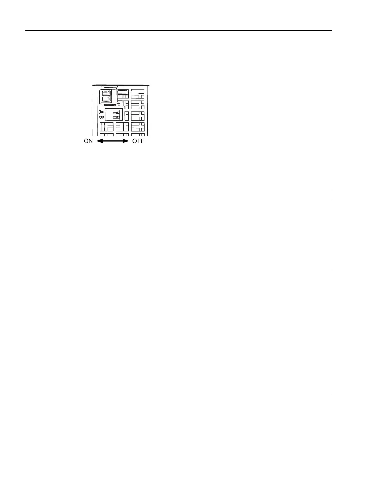
Figure 2-7 A/B selector switch
The two switches A and B are used to influence the output characteristic:
influences the output
characteristic in the
load range
'Soft' characteristic curve (see, e.g.
Figure 6-10
6EP1333-3BA10 parallel operation output char-
acteristic (Page 43)) for the parallel operation of
two or more devices: The output voltage falls
with increasing output current (namely, also for
the overcurrent pulse!).
This means that for full output current the high-
est output voltage can normally no longer be
Delivery state
'Hard' characteristic curve (see, e.g. Figure 6-3
6EP1333-3BA10 single operation output char-
acteristic (Page 41)) for normal operation (sin-
gle operation): The output voltage is
independent of the output current.
influences the output
characteristic in the
overload range
If the output current rises above the rated value
and above the current limit, the device reduces
the output voltage (see, e.g.
Figure 6-14
6EP1333-3BA10 latching shutdown output
characteristic (Page 44
)). If the output voltage
falls below 20 V, the device shuts down latch-
ing, the red LED lights up. This limit voltage of
20 V is independent of the set output voltage.
The 'Short-time overload current' feature is not
available in this operating mode. To also permit
charging of large capacitances in this operating
mode at the output, a shutdown is performed
during the first 10 s after power on or remote
switch on in conjunction with the non-latching
signaling module. During these first 10 s, the
device responds for overload as if the switch is
Delivery state
If the output current rises above the rated value
and above the current limit, the device reduces
the output voltage. The yellow LED lights up if
the output voltage falls below 20 V.
Conditioned when delivered: A - OFF; B - OFF
 Loading...