HRX-OM-K003
Chapter 8 Appendix
8.1 Specification HRW Series
8.1.2 Communication specification
This section provides the general outline of communications utilized in this system.
For detail specification, we provide a separate system manual “Communication
Specification”, which is available through your local distributor.
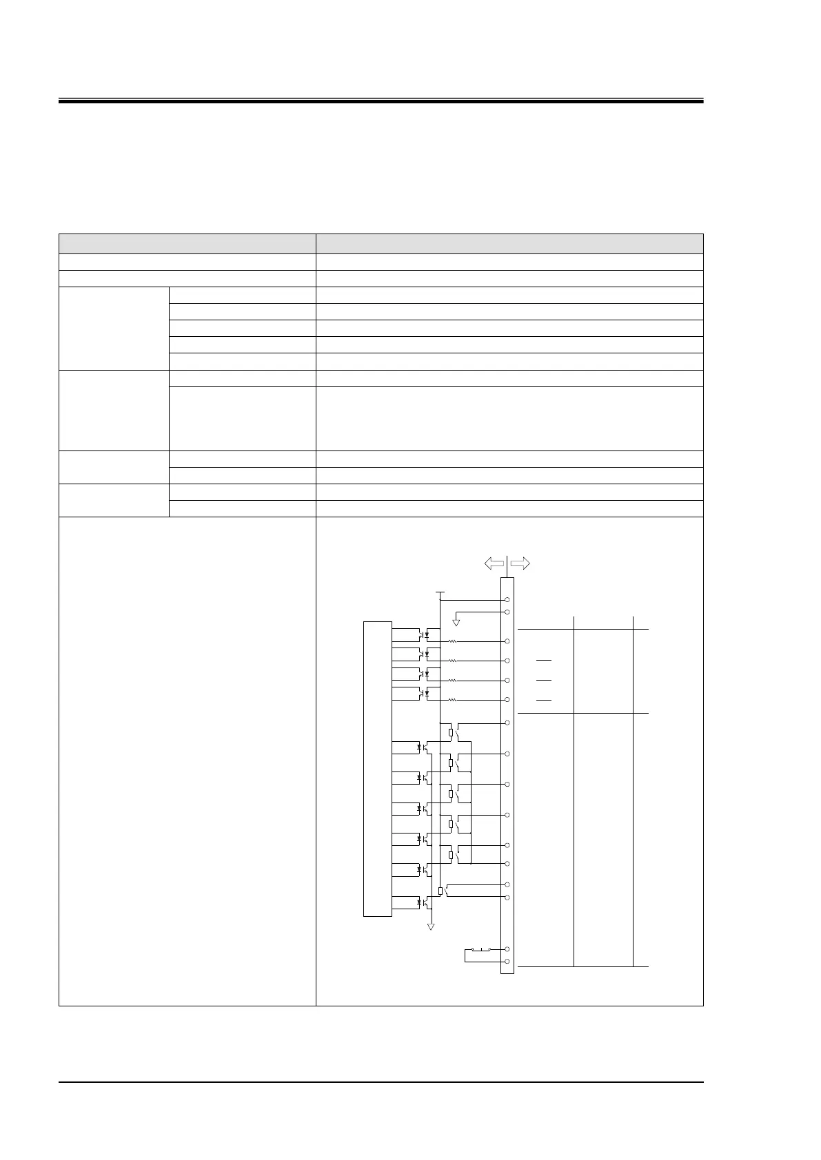
Contact signal
Table 8-4 Contact Signal
Connector type (this system)
D-sub25P female connector
When using power source output from chiller
:DC 200mA (resistance load, inductive load)
When using power source of your system
:AC / DC 800mA (resistance load, inductive load)
AC/DC 800mA (resistance load, inductive load)
AC/DC 800mA (resistance load, inductive load)
Run/Stop signal
Run signal
14
1
DC24V output
24COM output
3
13
25
18
5
20
7
19
6
Contact output COM
EMO signal
16
4
17
8
Warning signal
Fault signal
Remote signal
Temp Ready signal
Run/Stop signal 1
Output signal 1
Alarm signal
EMO signal
DIO REMOTE
signal 1
Run/Stop signal 2
DIO REMOTE
signal 2
Output signal 2
Output signal 3
Output signal 4
Output signal 5
Factory-shipped
configuration
Customized function
Thermo Chiller
DIGITAL
circuit
DC24V
4.7kΩ
4.7kΩ
4.7kΩ
4.7kΩ
24COM
24COM
Pin No.
Your system
15
Alarm signal
Contact output COM
Input signal
Output signal
Emergency off
[EMO] SW

 Loading...