- 15 -
2.5 Startup Procedures
Be sure to check the procedure below before use.
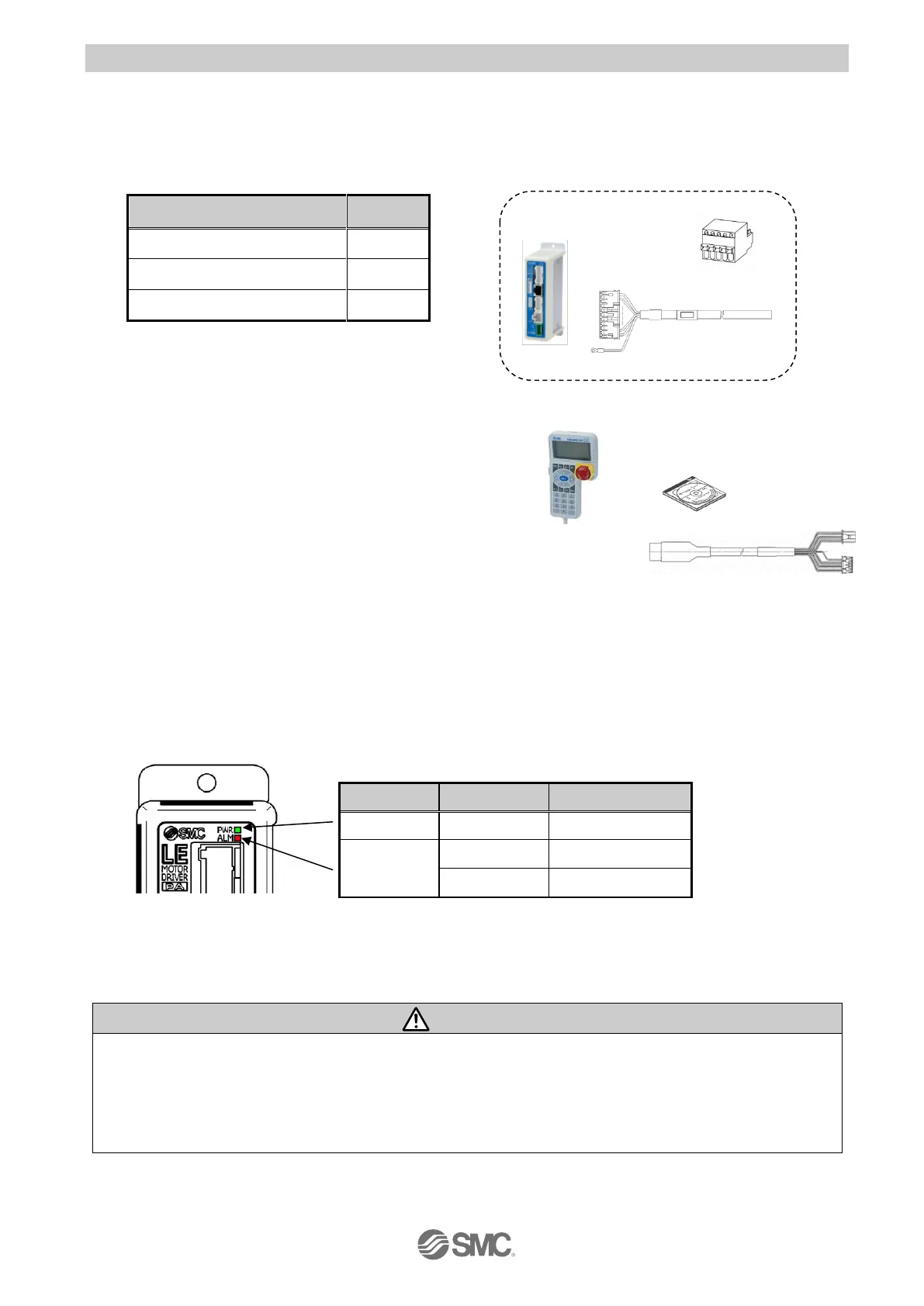
(1) Confirmation of the package content
After unpacking everything, check the description on the label to identify the driver and the number of
accessories. If any parts are missing or damaged, please contact your distributor.
*1) Included in the package only when the I/O
cable length is specified.
【
Option
】
● Teaching box
● Controller setting kit
● Actuator cable
● Noise filter set
● Current limiting resistor
(2) Installation
Please refer to the “3.4 How to install”
(3) Wiring and connection
Connect cables, etc. to the connector (CN1 to CN5) of the driver.
Please refer to the “5 External Wiring Diagram” for the wiring of the connectors.
(4) Power ON alarm (error)
Ensure the stop is not activated and then supply 24VDC power.
Driver
If the LED [PWR] lights in green, the driver is in the normal condition.
However, if the LED [ALM] lights in red, the driver is in the alarm (error) condition.
In case of alarm (error) condition:
Connect a PC or the teaching box to the CN4 serial I/O connector and check the details of the alarm.
Then, remove the cause of the error referring to the
“12. Alarm Detection”
Please refer to the manuals of the controller setting software or the teaching box for details of the
alarms.
 Loading...