EasyManuals Logo
Home>SMC Networks>Industrial Electrical>LECPA Series

SMC Networks LECPA Series User Manual

Default Icon
109 pages
To Next Page IconTo Next Page
To Previous Page IconTo Previous Page
Page #45 background imageLoading...
Page #45 background image
- 44 -
(2) Setting "Options set 1"
Options set 1, the basic parameter, needs to be set so that it is compatible with the PLC pulse output.
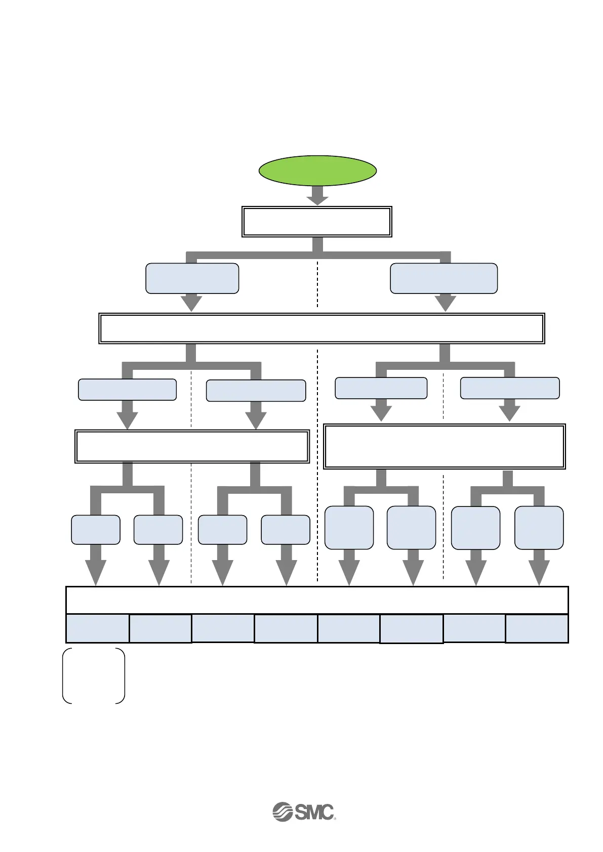
Set Option set 1 by following the chart below.
● Chart for open collector input connection
3
2
When the command signal is input to the NP input
terminal (direction), which direction is the motor
rotating in?
Photo coupler: ON
Photo coupler: OFF
Photo coupler: ON
Photo coupler: OFF
PP
NP
When the command pulse signal is input, in what state is the LECPA pulse input circuit?
CW and CCW
control mode
Pulse and Direction
control mode
PLC pulse output method?
PP
NP
Forward
direction
(CW)
Forward
direction
(CW)
Backward
direction
(CCW)
Backward
direction
(CCW)
5
0
4
Start
1
Setting value of Option set 1
Initial value
at the time
of factory
shipment
When rotating in the forward (CW) direction, what is
the pulse input terminal?
6
7

Table of Contents

Questions and Answers:

Question and Answer IconNeed help?

Do you have a question about the SMC Networks LECPA Series and is the answer not in the manual?

SMC Networks LECPA Series Specifications

General IconGeneral
BrandSMC Networks
ModelLECPA Series
CategoryIndustrial Electrical
LanguageEnglish