Home
SMC Networks
Industrial Electrical
LECPA Series
SMC Networks LECPA Series User Manual
5
of 1
of 1 rating
109 pages
Give review
Manual
Specs
To Next Page
To Next Page
To Previous Page
To Previous Page
Loading...
- 58 -
Power
SVON
PP-
NP-
TL
SETON
BUSY
INP
SVRE
TLOUT
External lock
Output
Input
Electric actuat
or
24V
0V
OFF
ON
ON
OFF
ON
OFF
0mm/s
・
・
・
・
Start of pulse input
・
・
・
・
・
・
・
・
Pushing
Speed
Deviation
Step data No.0
"Pushing
spee
d"
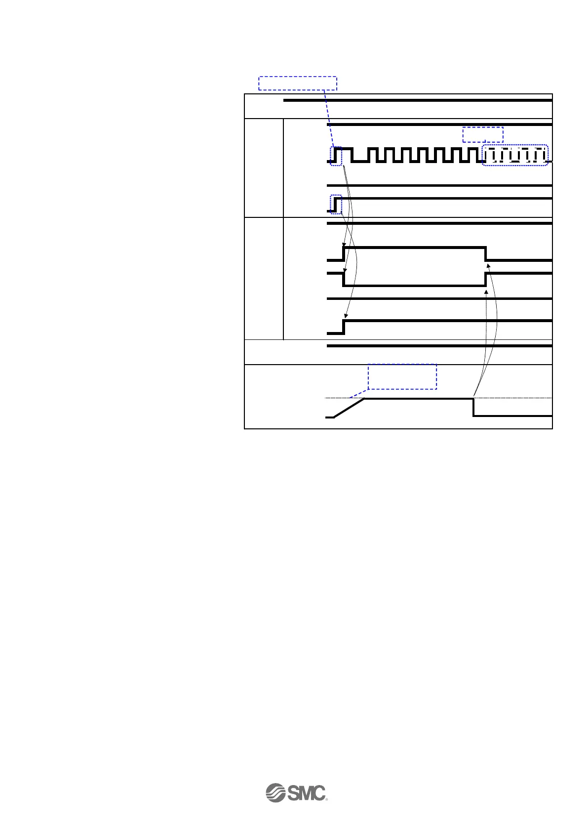
(3) Pushin
g operation
- Procedur
es-
- Timing c
ha
rt P
ushing oper
ation
-
(1) Input
pulse signal
↓
(2)
TL input
is turned O
N.
↓
(3) BUSY
output turns ON
INP
output is OF
F
TLOUT
output
is turned
on.
(Starts
pushing)
↓
(4)
Pushing
is
completed
when
INP
output
is
ON
and
BUSY
output
is
OFF
.
(Thrust
more
than
step
dat
a
No.0
"T
ri
g
ger L
V
"
is generated)
58
60
Table of Contents
Default Chapter
2
Table of Contents
2
1 Safety Instructions
6
2 Product Outline
8
Product Features
8
Product Configuration
9
How to Order
10
Actuator Cable (5M or Less)
11
Actuator Cable (8-20M)
11
Actuator Cable for with Lock (5M or Less)
12
Actuator Cable for with Lock (8-20M)
12
I/O Cable
13
Controller Setting Kit
13
Teaching Box
14
Noise Filter Set
15
Current Limiting Resistor
15
Startup Procedures
16
Confirmation of the Package Content
16
Installation
16
Wiring and Connection
16
Power on Alarm (Error)
16
Operation Pattern Setting
17
Trial Run (Electric Actuator Adjustment)
17
3 Product Specifications
18
Basic Specifications
18
Parts Description
19
Outside Dimension Diagram
20
Screw Mount Type (LECPA□□-□)
20
DIN Rail Mount Type (LECPA□□D-□)
20
How to Install
21
Ground Wire Connection
21
Installation Location
22
4 External Wiring Diagram
23
CN1: Power Connector
23
CN2: Motor Power Connector and CN3: Encoder Connector
23
CN4: Serial I/O Connector
23
Connection with the Teaching Box
23
Connection with a PC
24
CN5: Parallel I/O Connector
24
5 CN1: Power Supply Plug
25
Power Supply Plug Specifications
25
Electric Wire Specifications
25
Wiring of Power Supply Plug
25
Wiring of the Power Supply
25
Wiring of the Stop Switch
26
Wiring of the Lock Release
26
Stop Circuits
27
Example Circuit 1- Single Driver with Teaching Box
27
Example Circuit 2(Stop Relay Contact(1)
28
Example Circuit 3 Motor Power Shutdown(Stop Relay Contact(2)
29
6 CN5: Parallel L/O Connector
30
Parallel I/O Specifications
30
Parallel I/O Type (NPN/PNP Type)
30
Parallel I/O Input Circuit (same for both NPN and PNP Type)
30
Parallel I/O Output Circuit
30
Pulse Signal Input Circuit
31
The Parallel I/O Signal Is Detailed
33
Parallel I/O Wiring Example
36
7 Setting Data Entry
38
Step Data
38
Basic Parameter
40
Details of Basic Parameter
40
Setting "Options Set 1
45
Return to Origin Parameter
49
8 Operations Explanation
50
Return to Origin
50
Positioning Operation
50
Pushing Operation
51
Pushing Operation Is Successfully Performed
51
Pushing Operation Is Failed (Pushing the Air)
51
Response Time for the Driver Input Signal
52
Methods of Interrupting Operation
52
9 Operation (Example)
53
Positioning Operation
53
Pushing Operation
54
Actions after Pushing Operation
55
10 Operation Instruction
57
Power on → Return to Origin
57
Positioning Operation
58
Pushing Operation
59
Alarm Reset
60
Deviation Reset
60
Stop[Emg]
60
Area Output
61
11 Automatic Pulse Reference Detection
62
The Meaning of Automatic Pulse Reference Detection
62
Operation Procedure Using Automatic Detection Function
62
Automatic Pulse Reference Detection off
63
12 Alarm Detection
65
Parallel Output for the Alarm Group
65
Alarm Details
66
13 Wiring of Cables/Common Precautions
71
14 .Electric Actuators/ Common Precautions
72
Design and Selection
72
Mounting
73
Handling
74
Operating Environment
75
Maintenance
75
Precautions for Electric Actuator with Lock
76
15 Driver and Its Peripheral Devices /Specific Product Precautions
77
Design and Selection
77
Handling
77
Installation
78
Wiring of Cables
79
Power Supply
79
Grounding
79
Maintenance
79
16 Troubleshooting
81
Appendix 1. Default Setting Value Per Actuator
87
Appendix 1.1 LEY/LEYG Series Setting Value
87
Appendix 1.2 LEF Series Setting Value
89
Appendix 1.3 LES Series Setting Value
93
Appendix 1.4 LEHZ Series Setting Value
97
Appendix 1.5 LER Series Setting Value
103
Appendix 1.6 LEP Series Setting Value
105
5
Based on 1 rating
Ask a question
Give review
Questions and Answers:
Need help?
Do you have a question about the SMC Networks LECPA Series and is the answer not in the manual?
Ask a question
SMC Networks LECPA Series Specifications
General
Brand
SMC Networks
Model
LECPA Series
Category
Industrial Electrical
Language
English
 Loading...