Do not connect to equipment other than specified (LEC-W1, LEC-W2, LEC-T1).
When connected to equipment which is not specified, the product will be damaged by incorrect
signal wiring.
When connecting the cable, make sure that no electrically conductive materials are present in the
connector insertion port.
In the LEC-W1, the 0V of the driver and PC is not insulated.
If the 0V and the PC ground are common and the PC ground makes contact with another
voltage, an excessive voltage might be applied to the driver, causing damage to the
driver.
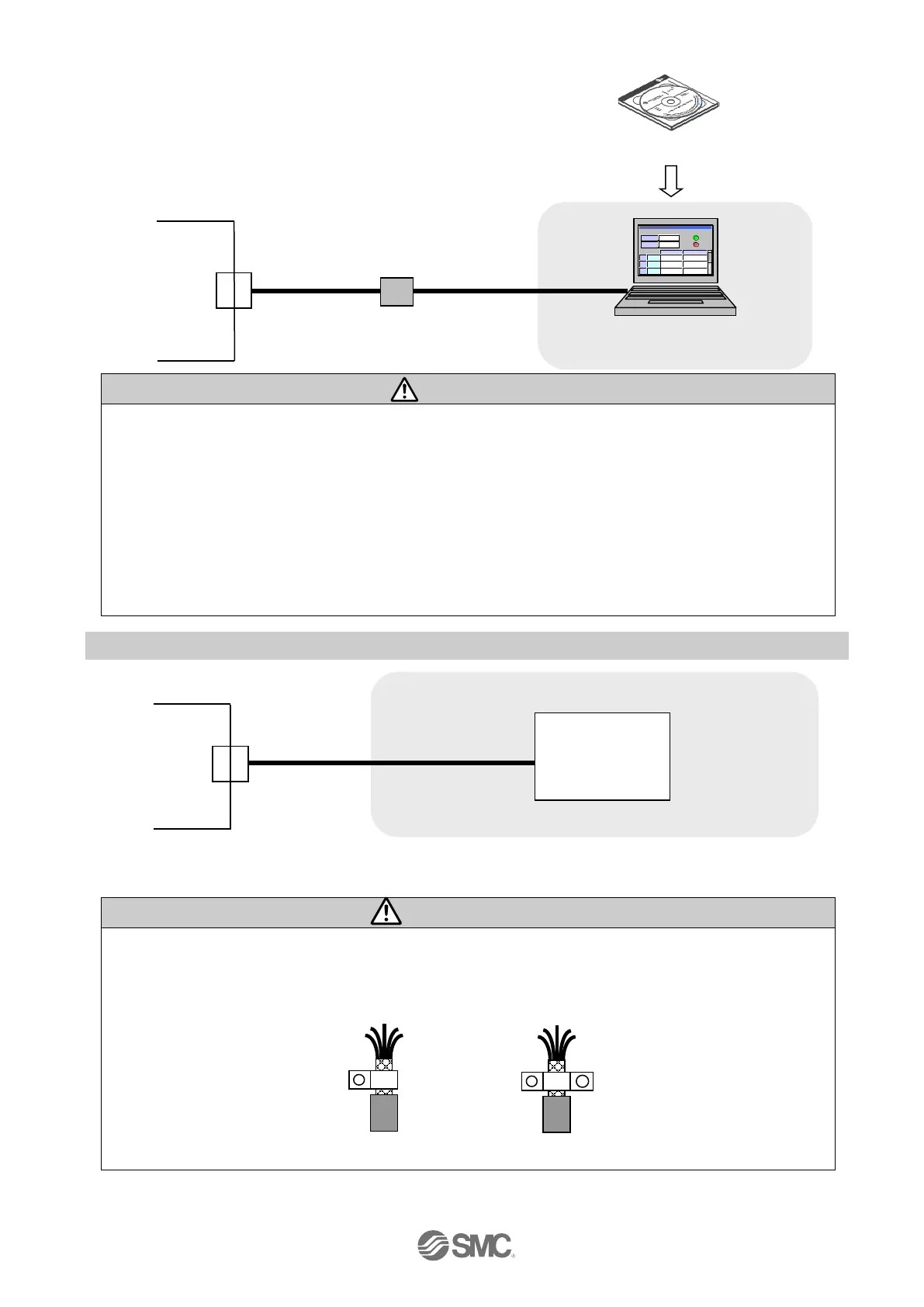
4.4 CN5: Parallel I/O connector
Driver
I/O cable
CN5
Please refer to “6.4 Parallel I/O Wiring Example” for how to wire the CN5 connector.
Please refer to "6.3 The parallel I/O signal is detailed" for details of each signal of parallel I/O.
Ground the both I/O cable ends for the protection from the noise.
Ground the cable end at the positioning unit side with metal cable clamp so that the entire
circumference of I/O cable shield contacts the clamp. Keep the stripped part of shield as short as
possible.
P clip U clip
 Loading...