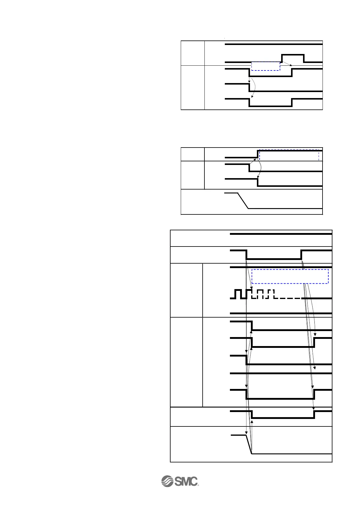
(4) Alarm reset
-Procedures- --Timing chart- Alarm reset
(1) Alarm generated
(SETON output and SVRE output are OFF
when alarm is generated)
↓
(2) RESET is turned ON.
↓
(3) ALARM is turned ON and the output SVRE
turned ON (the alarm is deactivated).
(5) Deviation reset
-Procedures- -Timing chart- Deviation reset
(1) The CLR input is turned ON during
the stop (when BUSY is OFF)
↓
(2)The deviation is cleared.
SETON is turned OFF
(6) Stop (EMG)
-Procedures- --Timing chart- Alarm reset
(1) The stop [EMG] input is turned OFF
during the operation (when BUSY is ON).
[stop command]
Turn off the pulse signal input at the same
time
↓
(2) ESTOP is turned OFF.
SETON is turned ON.
↓
(3) BUSY is turned OFF
(the electric actuator stops).
SVRE is turned OFF
The electric actuator with lock is locked.
↓
(4) The stop [EMG] input is turned ON.
[The stop release command]
↓
(5) STOP is turned ON.
*SVRE is turned ON.
The electric actuator with lock is unlocked.
* The “ALARM” is expressed as negative-logic circuit.
* It is necessary to reenter the controlled source for reset of
the alarm when alarm group E is generated.
 Loading...