HT-CT380/CT381
18
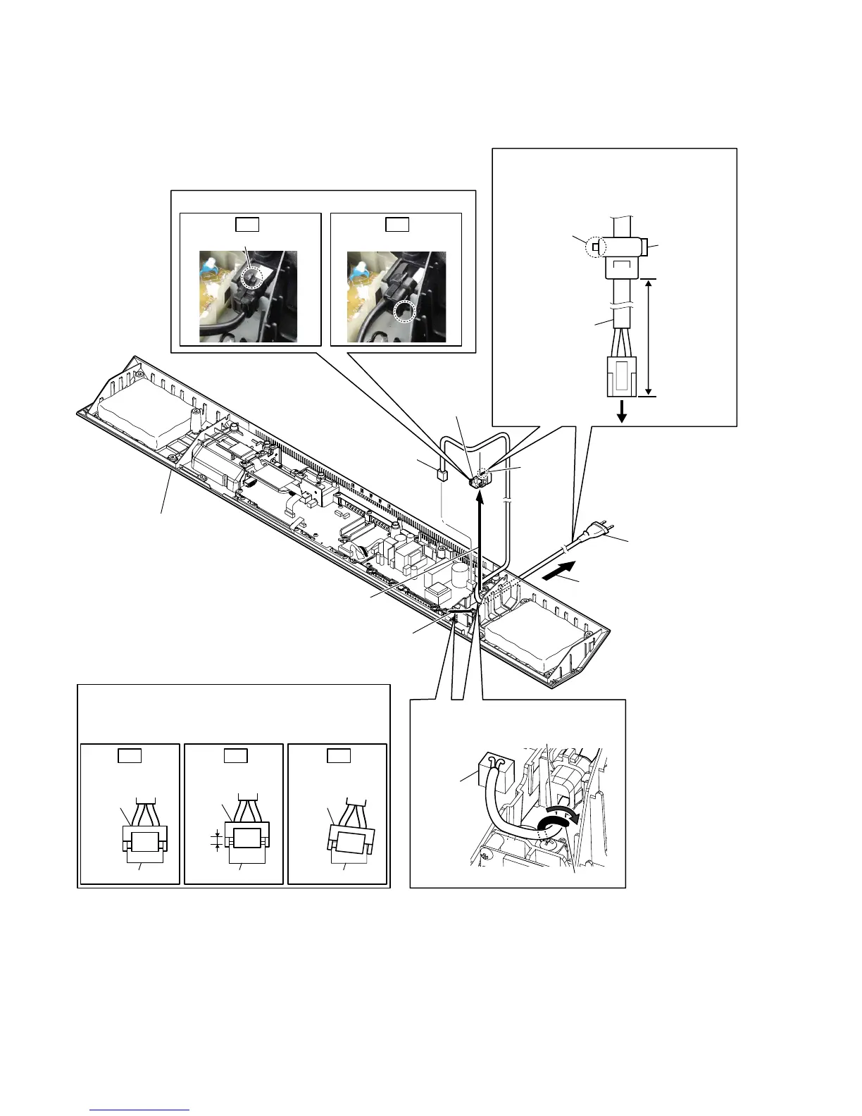
2-12. POWER CORD (AC1)
3RZHUFRUGVHWWLQJ
wiring stopper
Dress the wiring stopper
toward the arrow direction.
CN901
&RUGEXVKLQJ)%6VHWWLQJ
1 Remove the power cord
from the wiring stopper.
2 connector
(CN901)
4 Draw out the power cord
from the hole.
7 power cord
(AC1)
3 Remove the cord bushing (FBS001)
in the direction of the arrow.
6 cord bushing
(FBS001)
5 claw
3RZHUFRUGVHWWLQJ
power cord
(AC1)
cord bushing
(FBS001)
claw
70 +5, -0 mm
to POWER board
claw Claw is on the lower side.
Note:
When installing the power cord (AC1),
check the direction of claw of cord bushing
(FBS001) and install correctly.
cabinet (bottom) block
Insert only part way.Insert straight into
the interior.
connector
connector
Insert at a slant.
connector connector
connector
connector
OK NG NG
+RZWRLQVWDOOWKHSRZHUFRUGFRQQHFWRU
Insert the connector straight into the interior.
There is a possibility that using this unit without
the connector correctly installed will damage it.
OK NG
 Loading...