HT-CT380/CT381
20
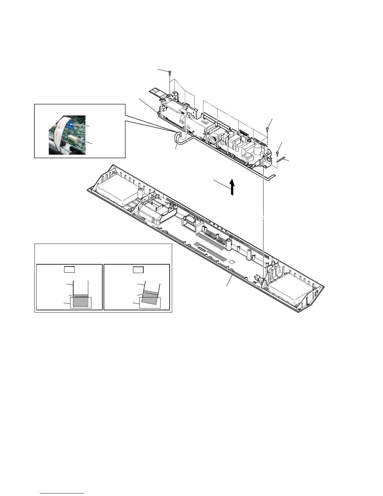
2-14. CHASSIS (MAIN) BLOCK
3 wiring stopper
2 screw
(BVTP3 u 10)
2 eleven screws
(BVTP3 u 10)
2 four screws
(BVTP3 u 10)
5 chassis (MAIN) block
cabinet (bottom) block
1 flexible flat cable (14 core)
(FFC1) (CN2001)
)OH[LEOHIODWFDEOH))&VHWWLQJ
Terminal face is
below side.
connector
(CN2001)
4 Remove the chassis (MAIN) block
in the direction of the arrow.
colored line
Insert straight into the interior.
flexible flat
cable
connector
OK
colored line
Insert at a slant.
flexible flat
cable
connector
NG
+RZWRLQVWDOOWKHIOH[LEOHIODWFDEOH
When installing the flexible flat cable, ensure that
the colored line is parallel to the connector after insertion.
 Loading...