5-4
S MIC Chassis
5-2. B BOARD ADJUSTMENTS
5-2-1. Primary Color Matrix Adjustment (1)
(RV115)
Input signal: Component color bars signal
(75 % chroma color bars signal)
Switches: UNDER SCAN 8 Pull (OFF)
16 : 9 8 Pull (4 : 3)
SYNC INT/EXT 8 EXT
LINE/RGB 8 RGB
1. Supply a sync signal from the test signal generator to
EXT SYNC IN connector of the rear panel.
2. Supply Y signal and R-Y signal from the test signal
generator to RGB/COMPONENT connector of the rear
panel.
3. Connect an oscilloscope to pin 30 (B OUT) of IC124.
4. Adjust RV115 (SUB HUE) to minimize (15 mVp-p or
less) the B signal level.
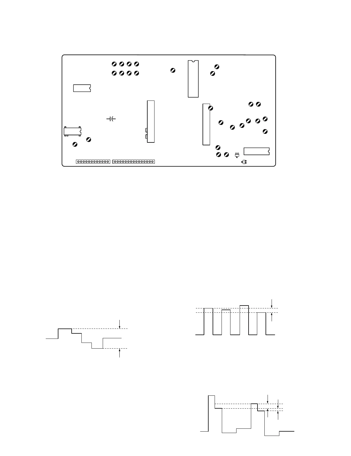
B Board Adjusting Components Location
5-2-2. Primary Color Matrix Adjustment (2)
(RV116, RV123)
Input signal: Component color bars signal
(75 % chroma color bars signal)
Switches: UNDER SCAN 8 Pull (OFF)
16 : 9 8 Pull (4 : 3)
SYNC INT/EXT 8 INT
LINE/RGB 8 RGB
1. Supply Y, R-Y, and B-Y signals from the test signal
generator to RGB/COMPONENT connectors.
2. Connect an oscilloscope to pin 30 (B OUT) of IC124.
3. Adjust RV116 (SUB COL) to minimize each peak level
(20 mVp-p or less). Adjust so that the 1st and the 4th
peaks should have the same level.
4. Connect an oscilloscope to pin 41 (R OUT) of IC124.
5. Adjust RV123 (MATRIX R-Y) so that the level
difference of R signal is shown below.
Specification:
Level difference of B and D = Minimum (20 mV or less)
Level difference of B and C = Minimum (30 mV or less)
Minimum
(15 mVp-p or less)
IC124
PIN-30
20 mV or less
IC124
PIN-30
20 mV or less
30 mV or less
A
B
C
D
IC124
PIN-41
RV103
CFM101
C202
IC109
IC106
CN101CN104
SEP101
RV124
RV125
RV123
RV121 RV120
RV205 RV116
RV122RV119
RV115RV118
RV101
RV102
RV1
T1
RV2
RV104
RV113
RV114
RV112
RV110
RV109
RV108
RV111
RV107
RV105 RV106
Q127
Q128
2
0![
+_
18
1610
IC113
IC124
1!;
@]
$-
#;
#/
E
E
@; #/@-
 Loading...


