5-6
S MIC Chassis
5-2-7. NTSC 3.58 MHz Color Demodulation (B-Y)
Adjustment (RV114, RV111)
Input signal: 3.58 MHz NTSC 75 % Color bars signal
(Set Y and B-Y of test signal generator to off.)
Switches: SYNC INT/EXT 8 INT
LINE/RGB 8 LINE
1. Connect an oscilloscope to emitter of Q128.
2. Adjust RV114 (3.58 NTSC HUE) so that the level other
than the burst portion is flat (Voltage difference = 10 mV
or less).
3. Set Y and B-Y of test signal generator to on.
4. Connect an oscilloscope to pin 30 of IC124.
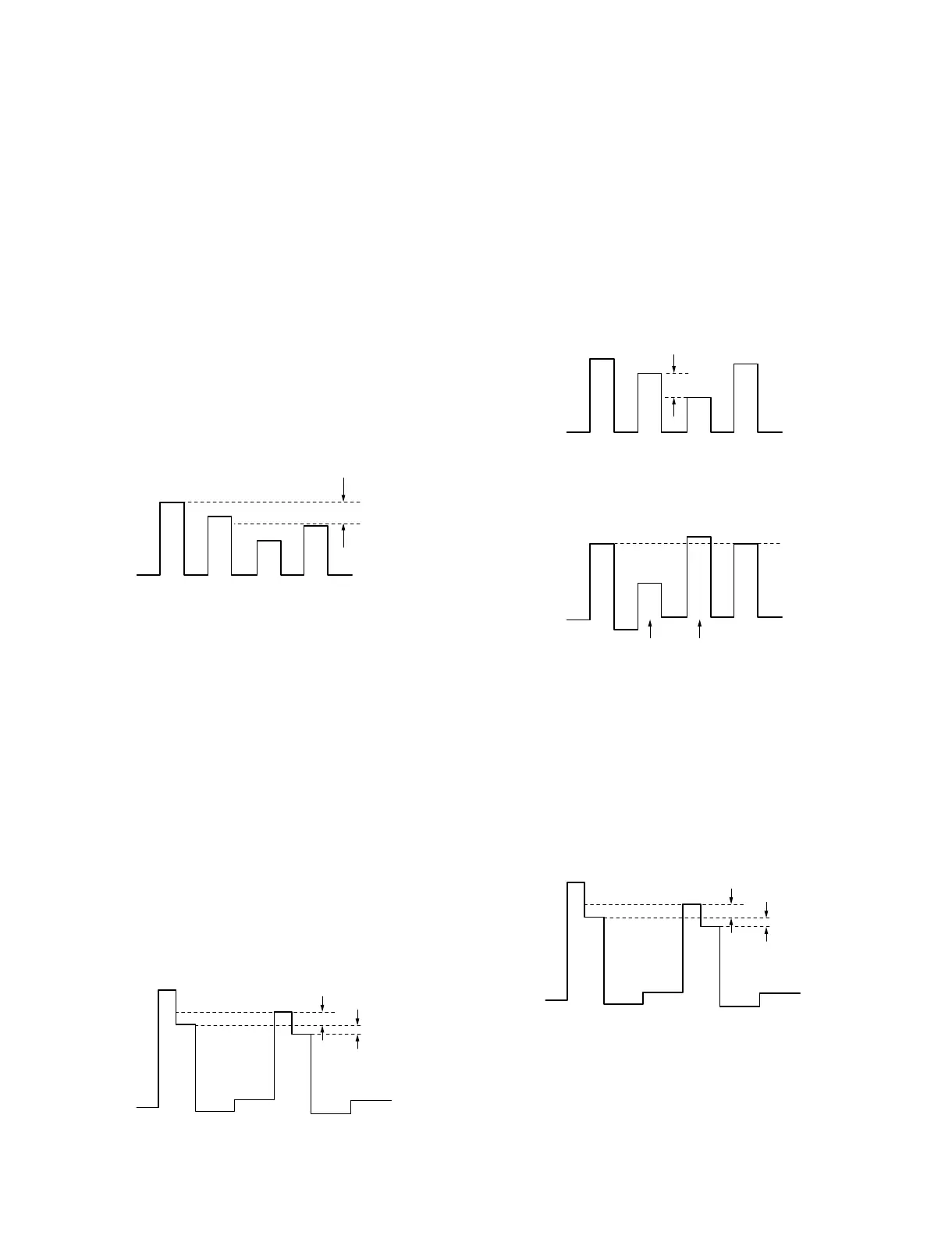
5. Adjust RV111 (3.58 NTSC COL) so that the level
difference of B signal is minimum (20 mVp-p or less).
Adjust so that the 1st and the 4th peaks should have the
same level.
5-2-8. NTSC 3.58 MHz Color Demodulation (R-Y)
Adjustment (RV104, RV107)
Input signal: 3.58 MHz NTSC 75 % Color bars signal
(Set Y and R-Y of test signal generator to off.)
Switches: SYNC INT/EXT 8 INT
LINE/RGB 8 LINE
1. Connect an oscilloscope to emitter of Q127.
2. Adjust RV104 (3.58 NTSC SHIFT) so that the R level
is flat (Voltage difference = ±15 mV or less).
3. Set Y and R-Y of test signal generator to on.
4. Connect an oscilloscope to pin 41 of IC124.
5. Adjust RV107 (3.58 NTSC COL) so that the level
difference of R signal is minimum.
Specification:
Level difference of B and D = Minimum (20 mV or less)
Level difference of B and C = Minimum (60 mV or less)
6. After adjustment, perform section “5-2-7. NTSC 3.58
MHz Color Demodulation (B-Y) Adjustment” again.
5-2-9. NTSC 4.43 MHz Color Demodulation
Adjustment (RV108, RV112)
Input signal: 4.43 MHz NTSC 75 % Color bars signal
(Set Y and B-Y of test signal generator to off.)
Switches: SYNC INT/EXT 8 INT
LINE/RGB 8 LINE
1. Connect an oscilloscope to pin 30 of IC124.
2. Adjust RV108 (4.43 NTSC COL) so that the level is flat
(Voltage difference = 25 mV or less).
3. If cyan and magenta levels are different, adjust RV112
(4.43 NTSC HUE) and RV108 (4.43 NTSC COL)
alternately.
4. Connect an oscilloscope to emitter of Q127.
5. Adjust RV103 (4.43 NTSC SHIFT) so that the R level
is flat (Voltage difference = ±15 mV or less).
6. Connect an oscilloscope to pin 41 of IC124.
7. Adjust RV106 (4.43 NTSC COL) so that the level
difference of R signal is minimum.
Specification:
Level difference of B and D = Minimum (20 mV or less)
Level difference of B and C = Minimum (60 mV or less)
8. After adjustment, readjust from steps 1 to 7.
20 mVp-p
or less
IC124
PIN-30
60 mV or less
20 mV or less
A
B
C
D
IC124
PIN-41
25 mV or less
IC124
PIN-30
Cyan Magenta
IC124
PIN-30
60 mV or less
20 mV or less
A
B
C
D
IC124
PIN-41
 Loading...


