5-7
S MIC Chassis
5-2-10. PAL Color Demodulation Adjustment
(RV113, RV2/SEP101, RV110, RV105)
Input signal: PAL Special Color bars signal
PAL Color bars signal
Switches: SYNC INT/EXT 8 INT
LINE/RGB 8 LINE
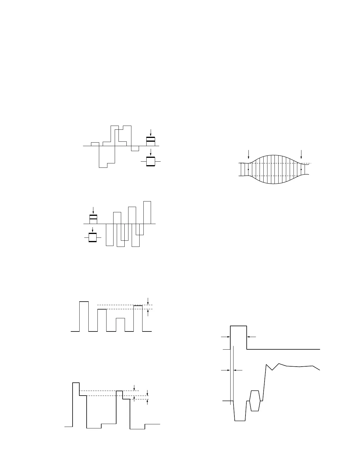
1. Connect an oscilloscope to emitter of Q127.
2. Adjust RV113 (PAL HUE) so that the B-Y (0/180d)
anti-PAL signal on the R-Y demodulated signal is flat.
3. Connect an oscilloscope to emitter of Q128.
4. Adjust RV2 on the SEP101 so that the R-Y (90/90d)
anti-PAL signal on the B-Y demodulated signal is flat.
5. Turn CHROMA control of the front panel maximum
clockwise, and make sure of no color is visible at the
anti-PAL signal portion on the CRT screen.
6. Input the PAL color bars signal.
7. Connect an oscilloscope to pin 30 of IC124.
8. Adjust RV110 (PAL COL) to minimize each peak level.
9. Connect an oscilloscope to pin 41 of IC124.
10.Adjust RV105 (PAL COL) so that the level difference
of R signal is minimum.
Specification:
Level difference of B and D = Minimum (20 mV or less)
Level difference of B and C = Minimum (60 mV or less)
11.After adjustment, readjust from steps 7 to 10.
5-2-11. Sub-Sharpness Adjustment (RV205)
Input signal: Sweep signal
Bandwidth: 10 MHz or more (flat)
Burst: OFF
Composite Sync: ON
Switches: SYNC INT/EXT 8 INT
LINE/RGB 8 LINE
1. Connect an oscilloscope to pin 36 of IC124.
2. Adjust RV205 (SUB SHARP) so that the 0.5 MHz and
6 MHz portions of the sweep signal is equal level (0
±0.5 dB).
5-2-12. Chroma H Pulse Adjustment
(RV101, RV102)
Input signal: SECAM Color Bars signal
Switches: SYNC INT/EXT 8 INT
LINE/RGB 8 LINE
1. Connect an oscilloscope to pin 10 of IC106 and pin 13
of CN101.
2. Adjust RV101 (PULSE WIDTH) so that the pulse width
is shown in the following specification.
Specification: Pulse width = 6.4 ±0.3 us
3. Adjust RV102 (PULSE POSI) so that the phase
difference of H sync to chroma H pulse is shown in the
following specification.
Specification: Phase difference = 0 ±0.5 us
B-Y (0/180d)
Anti-PAL signal
Q127 Emitter
R-Y (90/90d)
Anti-PAL signal
Q128 Emitter
40 mVp-p
IC124
PIN-30
60 mV or less
20 mV or less
A
B
C
D
IC124
PIN-41
0.5 MHz 6 MHz
IC124 PIN-36
6.4 ±0.3 us
0 ±0.5 us
IC106
PIN-10
CN101
PIN-13
 Loading...


