5-8
S MIC Chassis
5-3. S BOARD ADJUSTMENTS
S Board Adjusting Components Location
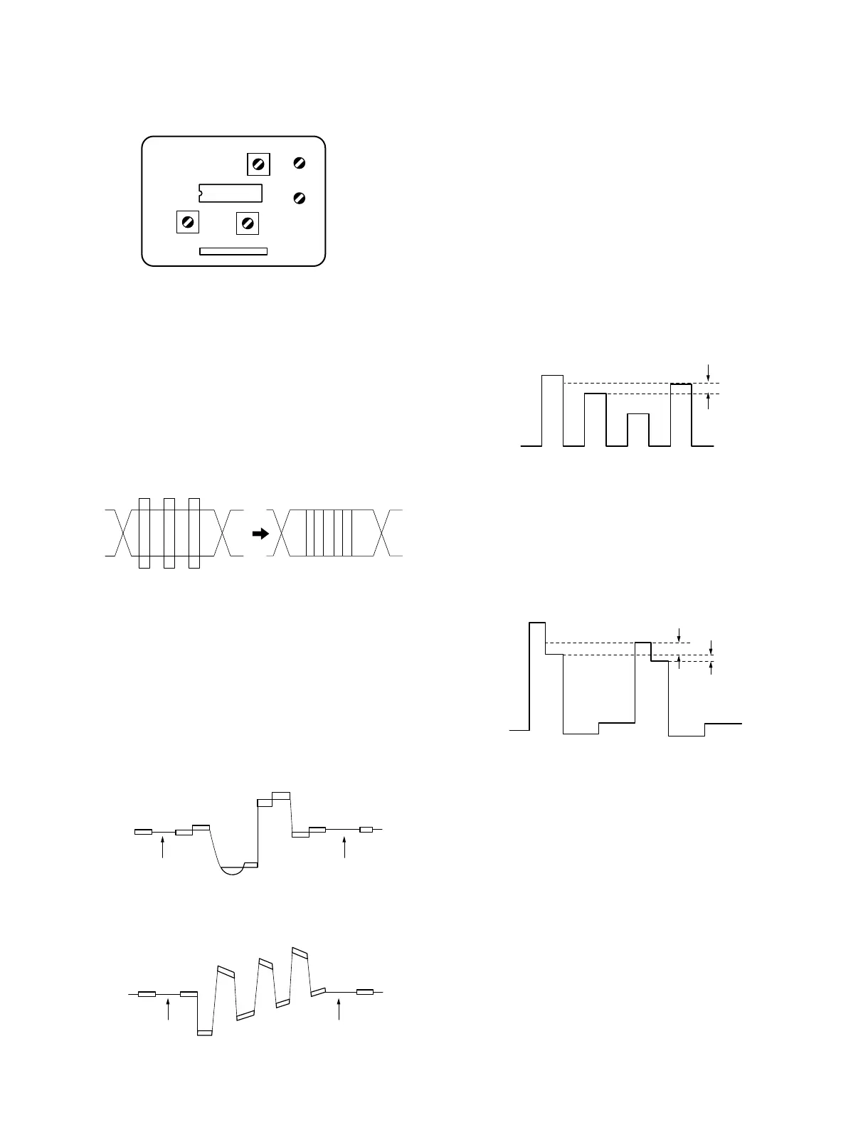
5-3-1. SECAM Bell Filter Adjustment (T1101)
Input signal: SECAM color bars signal
Switches: SYNC INT/EXT 8 INT
LINE/RGB 8 LINE
1. Connect an oscilloscope to pin 24 of IC1101.
2. Adjust T1101 (BELL FILTER) so that the envelope of
chroma signal is flat.
5-3-2. SECAM Color Balance Adjustment
(L1102, L1103)
Input signal: SECAM color bars signal
Switches: SYNC INT/EXT 8 INT
LINE/RGB 8 LINE
1. Connect an oscilloscope to pin 9 of CN1101.
2. Adjust L1102 so that no chroma component (no
colored) portions of R-Y signal is flat.
3. Adjust L1103 so that no chroma component (no
colored) portions of B-Y signal is flat.
5-3-3. SECAM Demodulation Level Adjustment
(RV1101, RV1102)
Input signal: SECAM color bars signal
Switches: SYNC INT/EXT 8 INT
LINE/RGB 8 LINE
1. Connect an oscilloscope to pin 30 of IC124 on the B
board.
2. Adjust RV1101 (SECAM COL) so that the peak level
difference of B signal is minimum (20 mVp-p or less).
Adjust so that the 1st and the 4th peaks should have the
same level.
3. Connect an oscilloscope to pin 41 of IC124 on the B
board.
4. Adjust RV1102 (SECAM R-Y) so that the level
difference of R signal is minimum.
Specification:
Level difference of B and D = Minimum (20 mV or less)
Level difference of B and C = Minimum (60 mV or less)
R-Y
CN1101
PIN-9
B-Y
CN1101
PIN-9
20 mV or less
60 mV or less
IC124
PIN-41
(B BOARD)
A
B
C
D
20 mVp-p or less
IC124
PIN-30
(B BOARD)
IC1101
PIN-24
RV1101
RV1102
CN1101
L1103
L1102
T1101
9
IC1101
@]
 Loading...


