DocID14024 Rev 4 17/39
UM0470 Single wire interface module (SWIM)
38
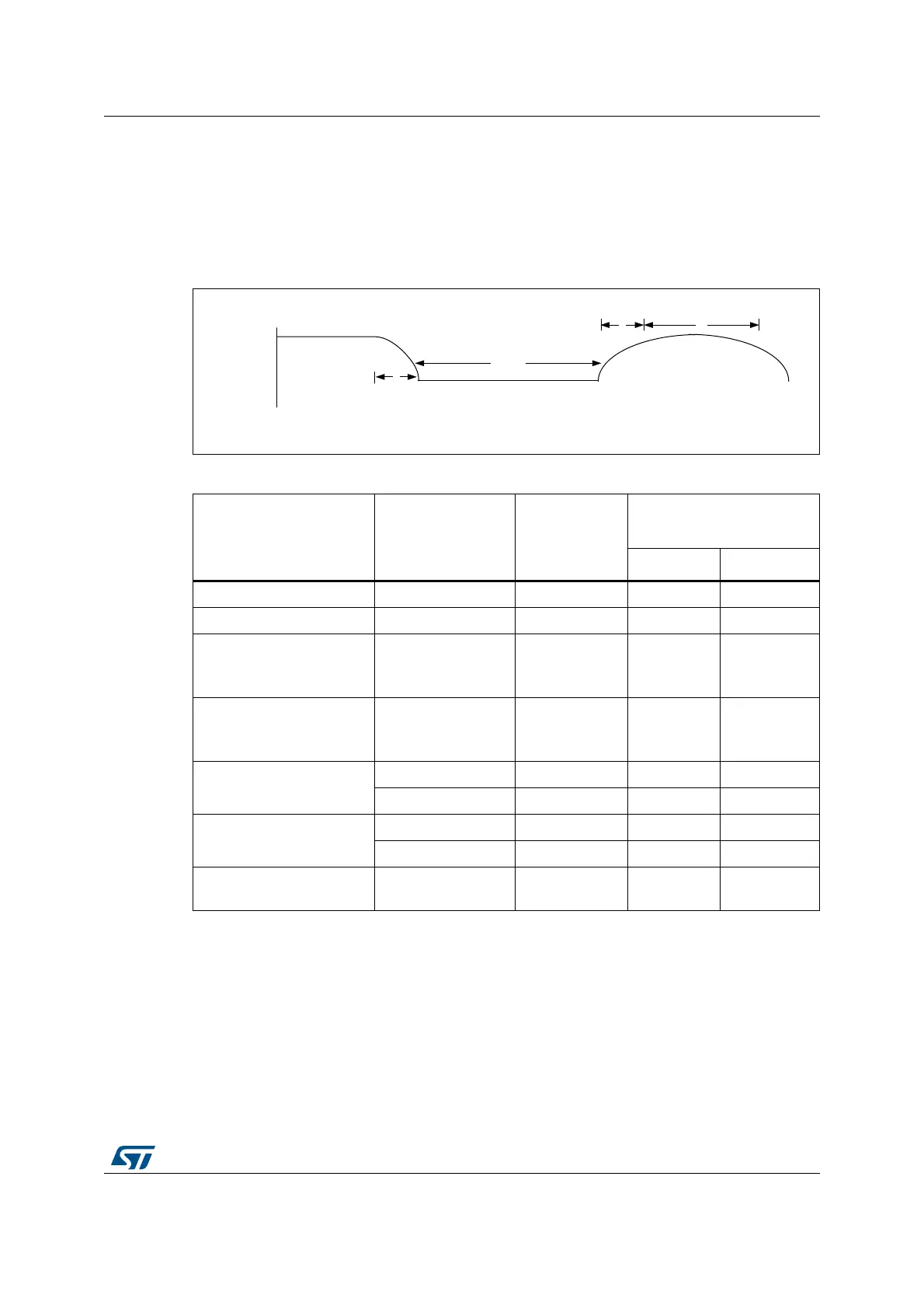
3.9 Physical layer
During the communication, the SWIM pin will be in pseudo-open drain configuration. The
SWIM pin in the device is capable of sinking 8
mA when it drives the line to 0. The external
pull-up on the SWIM line should be sized in a way that the maximum rise time t
r
of the
SWIM line is less than 1 sampling period of the bit (which is 100
ns +/- 4 %).
Figure 10. Timings on the SWIM pin
Table 3. SWIM pin characteristics
Parameter Symbol
Generic
formula
Timings for HSI = 10 MHz
LSI = 32 to 64 kHz
Min Max
Fall time on SWIM pin t
f
TBD - 50 ns
Rise time on SWIM pin t
r
TBD - 96 ns
Inter-bit time
(The time which SWIM pin
stays high between 2 bits)
t
ib
TBD >0 -
Inter-frame time
(Time between end of a
frame and the next one)
t
if
TBD 0 -
Low time for a bit at 0
High speed: t
b0
TBD 768 ns 832 ns
Low speed: t
b0
TBD 1.6 µs 2.4 µs
Low time for a bit at 1
(high speed)
High speed: Tb1 TBD 192 ns 208 ns
Low speed: Tb1 TBD 150 ns 250 ns
Injected current on SWIM
pin
-TBD-8 mA
06Y9
W
I
W
E
W
E
W
I
W
LE
6:,0SLQ

 Loading...
