Single wire interface module (SWIM) UM0470
8/39 DocID14024 Rev 4
3 Single wire interface module (SWIM)
3.1 Operating modes
After a power-on reset (powering of the device) the SWIM is reset and enters in its OFF
mode.
1. OFF: in this mode the SWIM pin must not be used as an I/O by the application. It is
waiting for the SWIM entry sequence or to be switched to I/O mode by the software
application.
2. I/O: this state is entered by the software application by setting the SWIM disable bit
(SWD) in the core configuration register (CFG_GCR). In this state, the user application
can use the SWIM pin as a standard I/O pin, the only drawback is that there is no way
to debug the functionality of this pin with the built-in debug capabilities.
In case of a reset, the SWIM goes back to OFF mode.
3. ACTIVE: this mode is entered when a specific sequence is detected on the SWIM pin
while it is in the OFF state. In this state, the SWIM pin is used by the host tool to control
the STM8 device with three commands: SRST (system reset), ROTF (read on-the-fly)
and WOTF (write on-the-fly).
Note: Please note that the SWIM can be set as ACTIVE and communicate while the device is in
RESET state (NRST pin forced low).
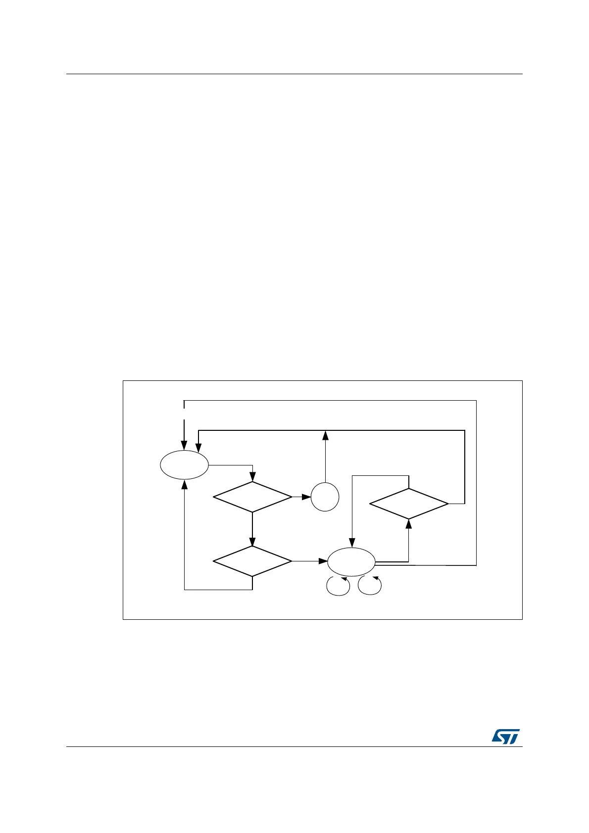
Figure 3. SWIM activation sequence
06Y9
2))
6:'ELWVHO
6:,0HQWU\
VHTXHQFH
<
<
,2
UHVHW
1
<
&65567
ELWVHW
$&7,9(
6567
527) :27)
1
325

 Loading...
