DocID14024 Rev 4 9/39
UM0470 Single wire interface module (SWIM)
38
3.2 SWIM entry sequence
After a POR (power on reset), and as long as the SWIM is in OFF mode, the SWIM pin is
sampled for entry sequence detection. In order to do this, the internal LSI (low speed RC -
resistor/capacitor) clock is automatically turned ON after the POR and remains forced ON
as long as the SWIM is in OFF mode.
If the register that forces the SWIM in I/O mode is written before the entry sequence is
finalized, the SWIM enters in I/O mode. Once the SWIM is ACTIVE, writing this bit has no
influence on communication and the SWIM interface remains in ACTIVE mode.
If an application uses the SWIM pin as standard I/O, it puts the SWIM interface in I/O mode
in the initialization section of the software code (typically, this is performed just after the
reset). However, even in this case, it is still possible to put the SWIM interface in ACTIVE
mode by forcing the RESET pin to 0 and keep it low for the duration of the SWIM entry
sequence.
As long as the SWIM is in OFF mode, the SWIM entry sequence is detected at any moment,
during reset or when the application is running.
If both the SWIM pin and the reset pin are multiplexed with I/Os, the way to enter the SWIM
in ACTIVE state is to power down the MCU device, power up and to maintain the reset until
the end of the SWIM entry sequence.
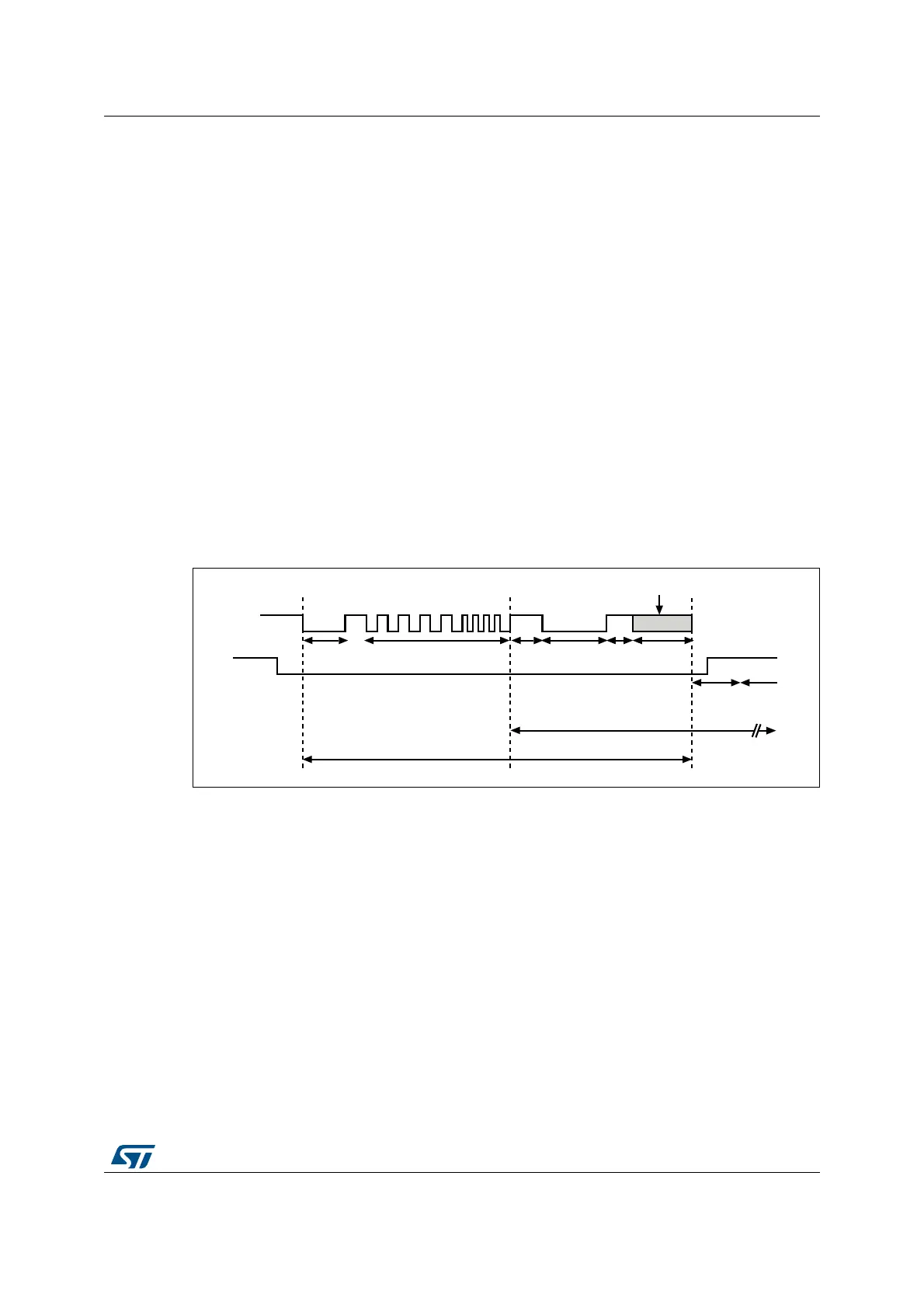
Figure 4. SWIM activation timing diagram
The SWIM activation is shown in Figure 4 and each segment of the diagram is described
below:
1. To make the SWIM active, the SWIM pin must be forced low during a period of 16 µs.
2. After this first pulse at 0, the SWIM detects a specific sequence to guarantee the
robustness in the SWIM active state entry. The SWIM entry sequence is: four pulses at
1
kHz followed by four pulses at 2 kHz. The frequency ratio is detected and allows the
SWIM entry. The ratio can be easily detected regardless of the internal LSI frequency
value. The waveform of the entry sequence is shown in
Figure 5. Note that the
sequence starts and ends with the SWIM pin at 1.
3. After the entry sequence, the SWIM enters in SWIM active state, and the HSI oscillator
is automatically turned ON.
37)-#32ANDSET
37)-PIN
2ESET
/PTIONBYTELOADING
(3)!$#/.
,3)/3#/.
AI
2ESETRISING

 Loading...
