DocID027916 Rev 2 27/79
UM1902 Hardware layout and configuration
78
5.19 Motor control
STM32746G-EVAL evaluation board supports both asynchronous and synchronous three-
phase brushless motor control via a 34-pin connector CN1, which provides all required
control and feedback signals to and from motor power-driving board.
The available signals on this connector are emergency stop, motor speed, 3 phases motor
current, bus voltage, heatsink temperature, coming from the motor driving board and 6
channels of PWM control signal, going to the motor driving circuit.
Some PCB reworks are needed for motor control application, to disconnect those
peripherals, which share I/Os with motor control connector and connect these I/Os to motor
control connector:
• Open SB5, SB29, SB32, SB36, SB37, SB41, SB43, SB45, SB49, SB52, SB55, SB57,
SB60, SB61, Remove R95, R100, R241, R252, keep no jumper on JP4 (Pin2-3), keep
no jumper on JP8/JP21/JP22, keep no jumper on JP19 (Pin 2-3), keep CN4 and CN13
unconnected.
• Close SB23, SB30, SB31, SB34, SB35, SB38, SB39, SB40, SB42, SB44, SB46, SB48,
SB50, SB53, SB56, SB58, SB59, SB62. Mount R14 with 0 ohm resistor.
PA4 and PA5 are DAC output; when using them for debugging purposes, keep CN4
unconnected and remove R126.
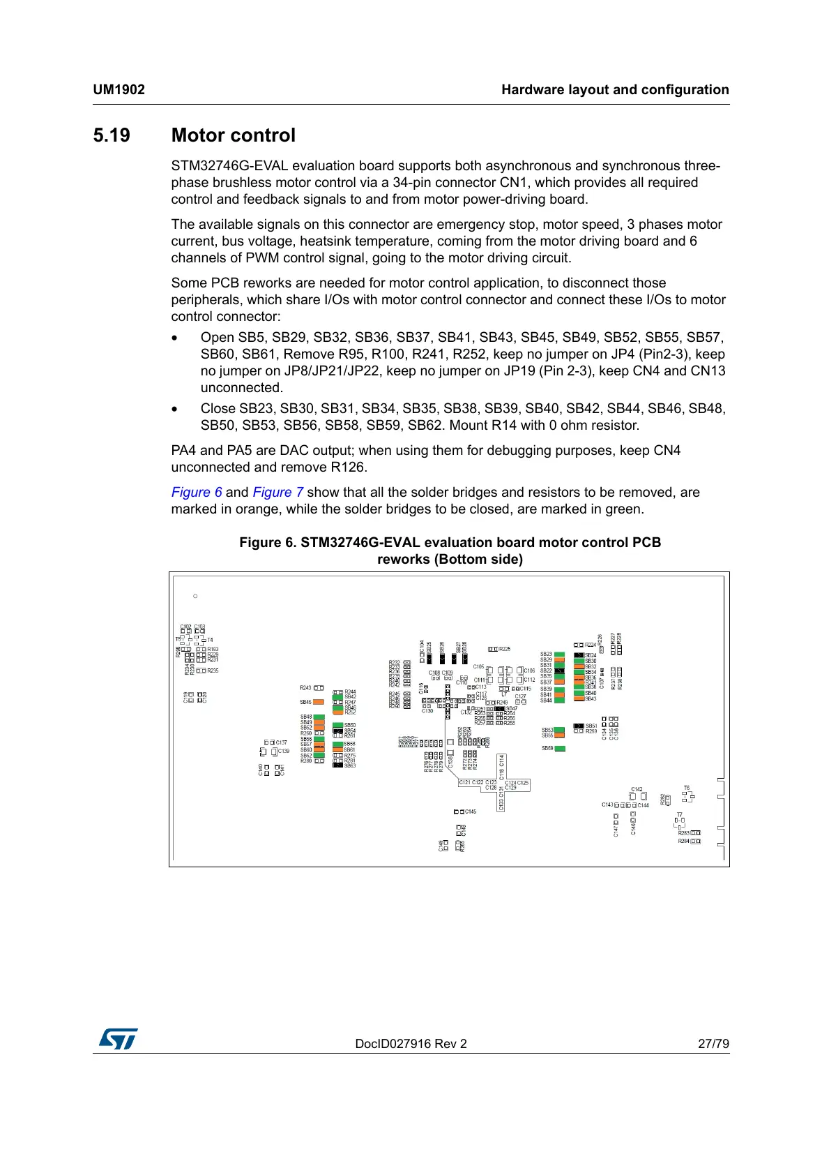
Figure 6 and Figure 7 show that all the solder bridges and resistors to be removed, are
marked in orange, while the solder bridges to be closed, are marked in green.
Figure 6. STM32746G-EVAL evaluation board motor control PCB
reworks (Bottom side)

 Loading...