DocID027916 Rev 2 39/79
UM1902 Connector
78
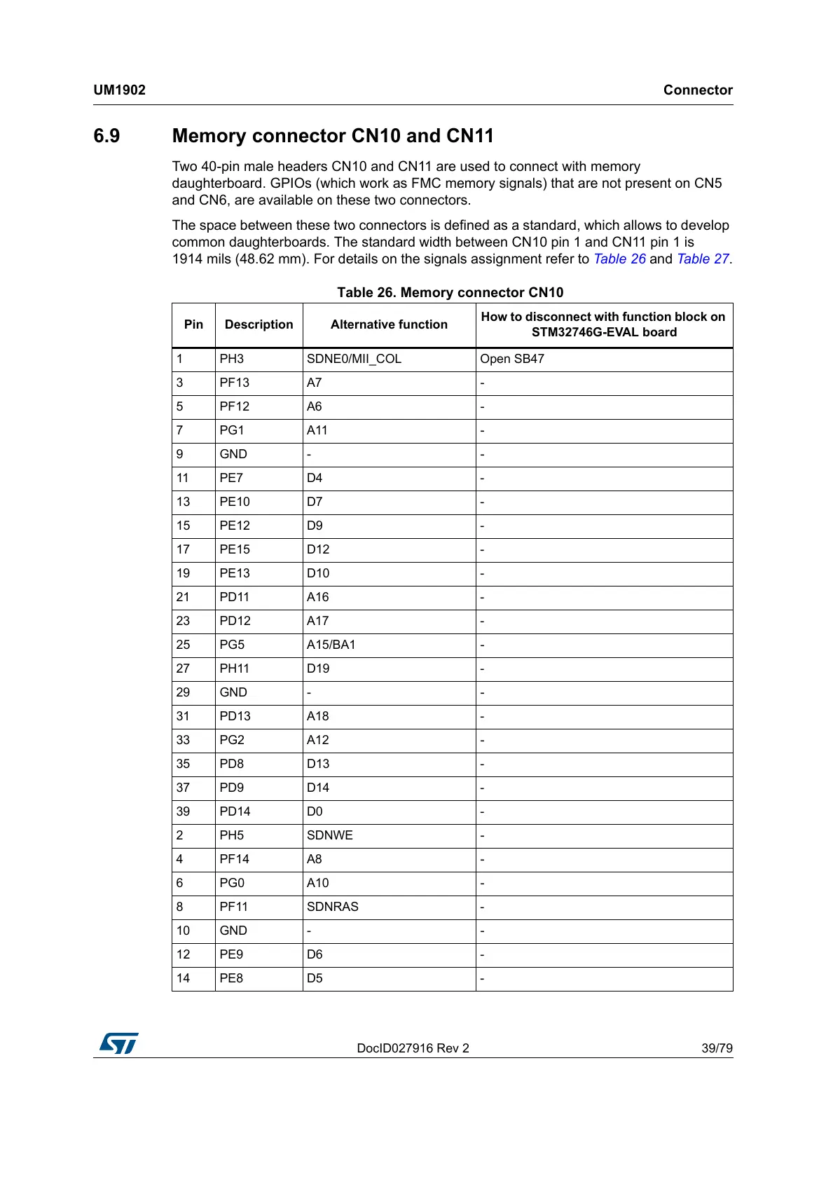
6.9 Memory connector CN10 and CN11
Two 40-pin male headers CN10 and CN11 are used to connect with memory
daughterboard. GPIOs (which work as FMC memory signals) that are not present on CN5
and CN6, are available on these two connectors.
The space between these two connectors is defined as a standard, which allows to develop
common daughterboards. The standard width between CN10 pin 1 and CN11 pin 1 is
1914 mils (48.62 mm). For details on the signals assignment refer to Table 26 and Table 27.
Table 26. Memory connector CN10
Pin Description Alternative function
How to disconnect with function block on
STM32746G-EVAL board
1 PH3 SDNE0/MII_COL Open SB47
3PF13 A7 -
5PF12 A6 -
7PG1 A11 -
9GND - -
11 PE7 D4 -
13 PE10 D7 -
15 PE12 D9 -
17 PE15 D12 -
19 PE13 D10 -
21 PD11 A16 -
23 PD12 A17 -
25 PG5 A15/BA1 -
27 PH11 D19 -
29 GND - -
31 PD13 A18 -
33 PG2 A12 -
35 PD8 D13 -
37 PD9 D14 -
39 PD14 D0 -
2 PH5 SDNWE -
4PF14 A8 -
6PG0 A10 -
8 PF11 SDNRAS -
10 GND - -
12 PE9 D6 -
14 PE8 D5 -

 Loading...