Connector UM1902
32/79 DocID027916 Rev 2
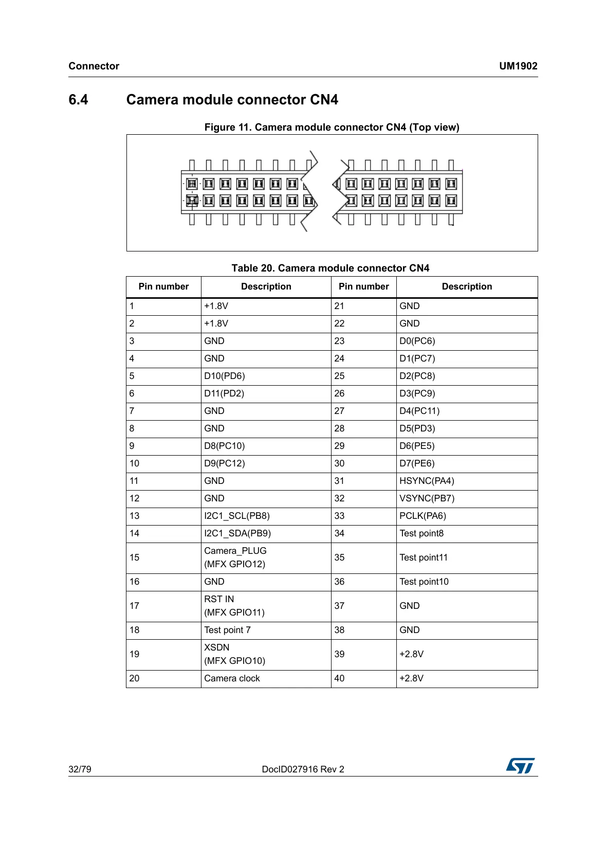
6.4 Camera module connector CN4
Figure 11. Camera module connector CN4 (Top view)
Table 20. Camera module connector CN4
Pin number Description Pin number Description
1 +1.8V 21 GND
2 +1.8V 22 GND
3 GND 23 D0(PC6)
4 GND 24 D1(PC7)
5 D10(PD6) 25 D2(PC8)
6 D11(PD2) 26 D3(PC9)
7 GND 27 D4(PC11)
8 GND 28 D5(PD3)
9 D8(PC10) 29 D6(PE5)
10 D9(PC12) 30 D7(PE6)
11 GND 31 HSYNC(PA4)
12 GND 32 VSYNC(PB7)
13 I2C1_SCL(PB8) 33 PCLK(PA6)
14 I2C1_SDA(PB9) 34 Test point8
15
Camera_PLUG
(MFX GPIO12)
35 Test point11
16 GND 36 Test point10
17
RST IN
(MFX GPIO11)
37 GND
18 Test point 7 38 GND
19
XSDN
(MFX GPIO10)
39 +2.8V
20 Camera clock 40 +2.8V

 Loading...