User Manual 2 Product Introduction
7
Any other or additional usage is not permitted except the intended usage.
Inverter may only accept PV modules with Protection Class II as its input.
Inverter may only be connected to utility grid via distribution board. Local
loads (home appliance, lights, motor loads, etc.) cannot be connected
between inverter and AC circuit breaker on the distribution board.
Additionally, the unit is intended for fixed installation. Located on a part
that is not removable without impairing the operation of the unit.
2.2 Product Description
2.2.1 Product Appearance
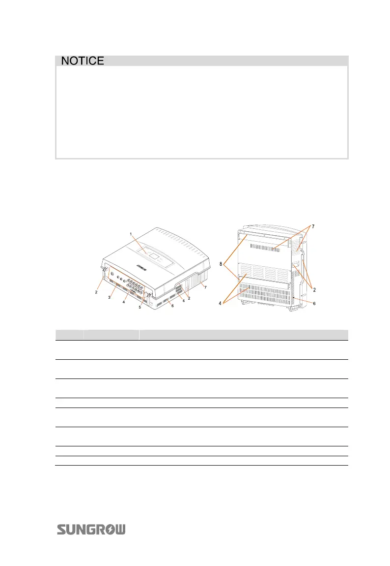
Fig. 2-2 Product Components Description
Item Name Description
1
LCD display
panel
Inverter operation data viewing and parameters
configuration can be performed via the LCD display panel.
2 Handles
The handles are designed for holding the unit when
transporting, installing or servicing.
3
Connection
terminals
They are DC input terminals, AC output terminal and RS485
communication terminal.
4 Air inlet Entrance of cool air.
5 DC switch
During normal operation it is in “ON” state. It can shut down
the inverter immediately in “OFF” position.
6
Second PE
terminals
Second protective earth terminals as specified in EN 50178.
7 Air outlet Exit of hot air during the inverter operation.
8 Mounting ear It is used for hanging inverter onto the backplate.
 Loading...