6 Electrical Connection User Manual
46
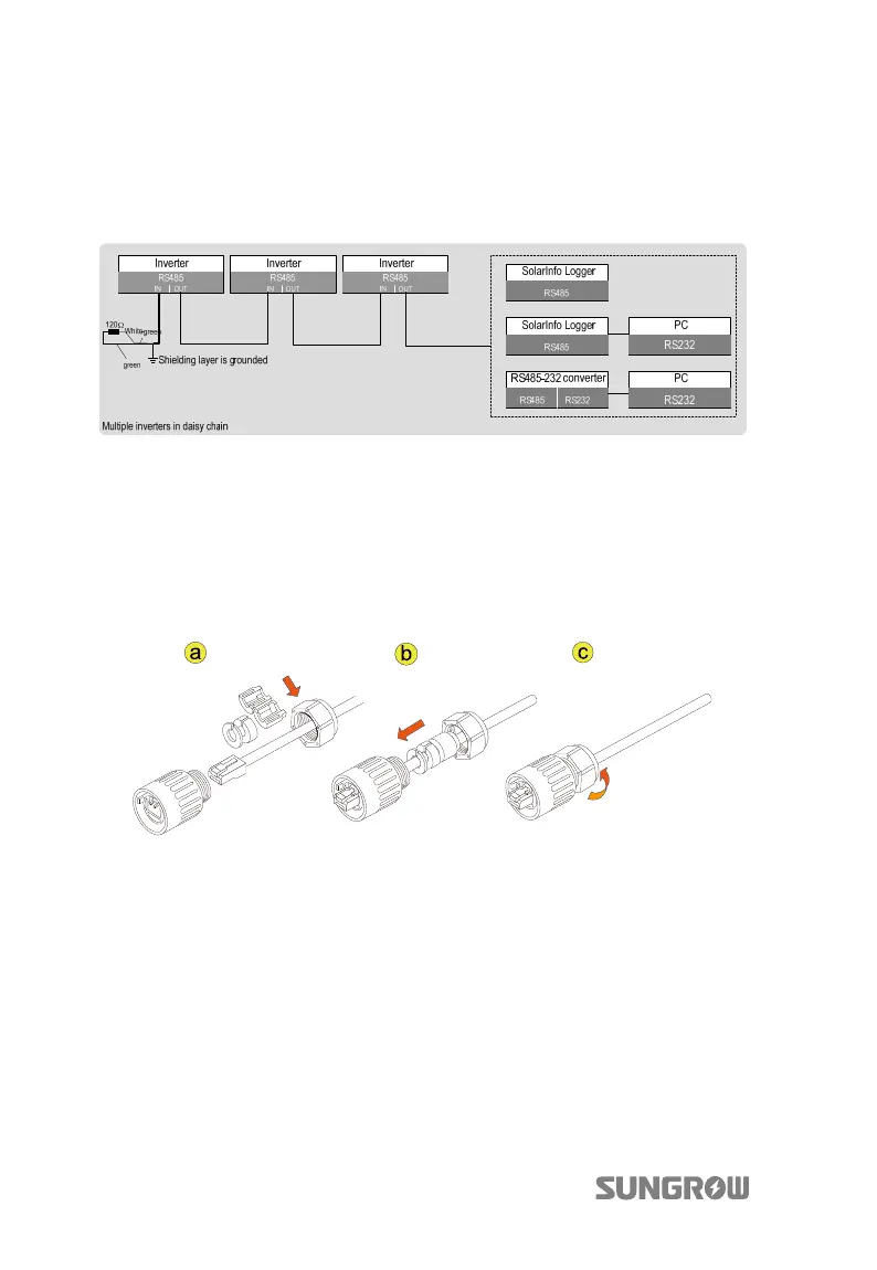
shielding layer of RS485 cable should be single-point grounded.
The maximum number that inverters are connected in the daisy chain depends on
converter, data logging device and other factors. Please refer to converter’s or data
logging device’s manual to obtain the limit.
Fig. 6-7 Multiple Inverters Communication with Other Devices
6.6.3 RS485 Communication Connection
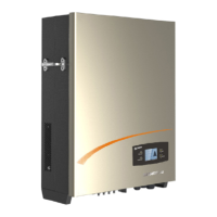
Step 1 Insert the RJ45 plug into the front plug connector until it makes a clicking
sound, install the plastic rings then tighten the cable gland with appropriate
torque.
Step 2 Insert connector of one cable end into RS485 in/RS485 out terminal on the
bottom of the inverter. Make connector and RS485 terminal engage and
rotate clockwise.
Step 3 According to the position of the inverter, repeat step 1…2 to connect the
other Ethernet cables to the RS485 in/RS485 out. Ethernet cables with RJ45
plugs can be directly used to connect between the inverters and form a
communication daisy chain.
Step 4 Pull cables outwards to confirm whether they are fastened firmly.
Step 5 As for the wires which connect to the terminating resistor or logging devices,
use the Ethernet wire stripper to strip the insulation layer and connect the
RS485 A and B cables (6 and 3) to terminating resistor or data logging device
or RS 485-232 converter.