User Manual 10 Operation of LCD Display Panel
73
Parameter Explanation Default Range
Upper
Power*
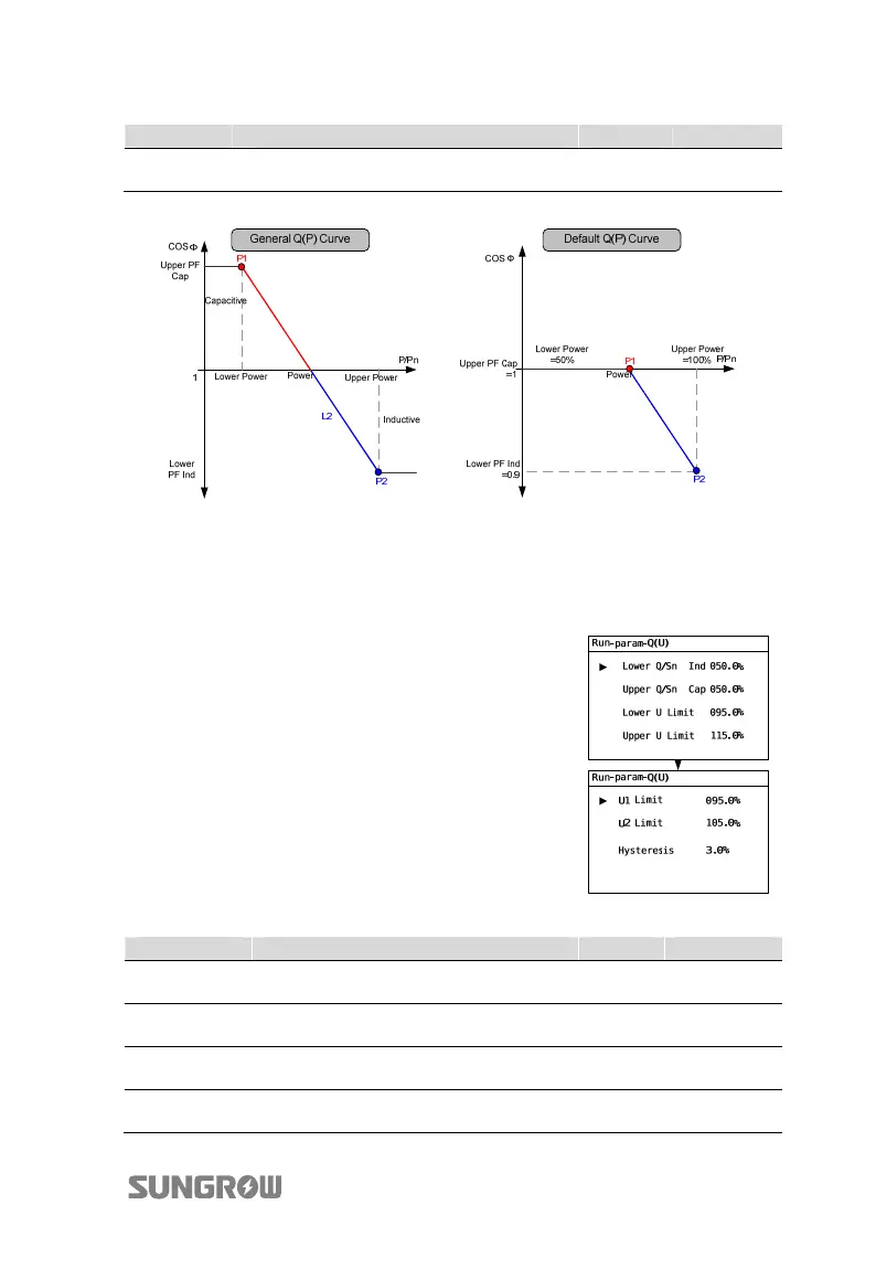
Output power of point P2 in the Q(P)
mode curve (in %)
100% 50%...100%
*Lower Power <Upper Power
Fig. 10-3 Reactive Power Regulation Curve in Q(P) Mode
“Q(U)” Mode(when the country selection is not “IT”)
The reactive power ratio changes with the grid voltage.
If the country selection is not “IT” (Italy), after selecting
Q(U) mode, Press j to enter the Run-param-Q(U)
sub-menu.
For each item setting, Press h to move cursor right and
Press j to set the appropriate value.
Confirm settings by Pressing ENTER.
Tab. 10-6 “Q(P)” Mode Parameters Explanation
Parameter Explanation Default Range
Lower Q/Sn
Ind
Inductive Q/Sn value of point P4 in the
Q(U) mode curve
25% 0%...50%
Upper Q/Sn
Cap
Capacitive Q/Sn value of point P1 in the
Q(U) mode curve
25% 0%...50%
Lower U Limit
Grid voltage limit (in %) of point P1 in the
Q(U) mode curve
80% 80%...90%
Upper U Limit
Grid voltage limit (in %) of point P4 in the
Q(U) mode curve
115% 110%...115%

 Loading...