11
3
Product Description
3.1 Overall Design of the Inverter
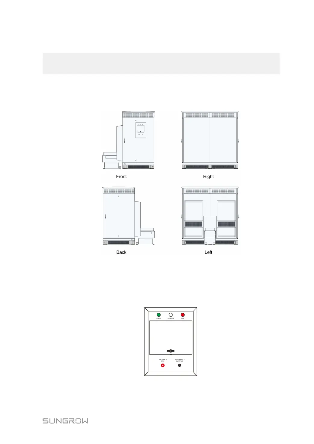
3.1.1 Inverter Views
CCoonnttrrooll aanndd MMoonniittoorriinngg WWiinnddooww
The Control and Monitoring window is located on the front door of the inverter.
As shown in the figure below, the LED indicators are at the upper part, the color liquid
crystal (LCD) touchscreen is at the middle part, and the emergency stop button is at the
lower part.
The LEDs at the upper side of the Control and Monitoring Window: POWER indicates
the power-on state; OPERATION indicates the proper operation of the inverter; FAULT
indicates a fault condition.
 Loading...