12
LLEEDD IInnddiiccaattoorrss
The working status of the inverter can be acquired through these LEDs.
LLEEDD CCoolloorr
DDeessccrriippttiioonn
POWER Green
The control circuit power supply is supplying power.
OPERATI-
ON
White
Inverter is in stop mode.
Green
Inverter is in grid-connected run mode.
Yellow Inverter is in alarm run mode.
FAULT Red
A fault occurs and has not been removed.
The indicator will be off when the fault is cleared.
EEMMEERRGGEENNCCYY SSTTOOPP BBuuttttoonn
When an emergency occurs, the DC and AC circuit breakers are disconnected
automatically after pressing the emergency stop button.
After the fault is removed, release the emergency stop button with the specific key, and
then manually start the inverter.
TThhee MMAAIINNTTEENNAANNCCEE IINNTTEERRFFAACCEE
The cover plate of the LCD can only be opened with the key. Remove the key and store
it properly after use.
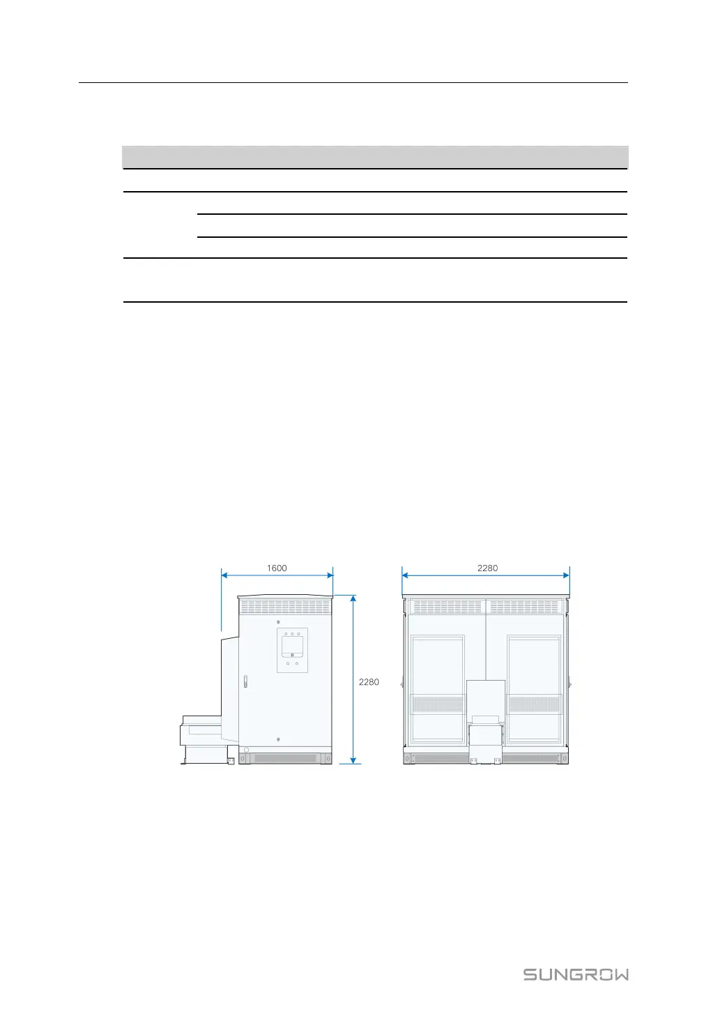
3.1.2 Mechanical Parameter
DDiimmeennssiioonnss
External dimensions are shown in the figure below.
CClleeaarraannccee SSppaacceess
The clearances around the inverter should be sufficient for the doors to be opened
3 Product Description System Manual
 Loading...