7-14 POWER UNIT
INSTALLATION
Installation is reverse of removal with special attention to fol-
lowing steps.
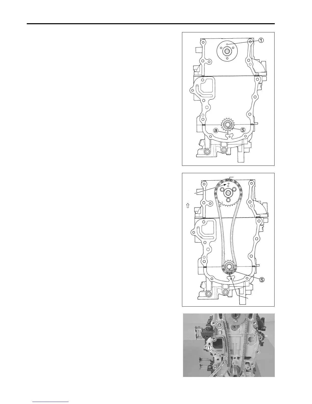
(1) Align crankshaft timing mark S with timing mark a on crank-
case as shown in figure by turning crankshaft.
(2) Install dowel pin 1 into camshaft.
Then turn the camshaft to locate the dowel pin position at
the top as shown in figure.
(5) Install timing chain guide 1 , then tighten bolts securely.
(3) Align yellow plate of timing chain and crankshaft timing mark
S as shown in figure, then install the timing chain.
(4) Bring another yellow plate of timing chain into alignment
with arrow mark on camshaft timing sprocket, then install
camshaft timing sprocket into camshaft.
Tighten sprocket bolts, pre-coated with thread lock, to speci-
fied torque.
II
II
I 99000-32050 : Thread Lock “1342”
!!
!!
! Camshaft timing sprocket bolt :
11 N
.
m (1.1 kg-m, 8.0 lb.-ft.)
Yellow plate
Arrow
mark
( )
Yellow plate
1

 Loading...


