9-12 POWER TRIM AND TILT
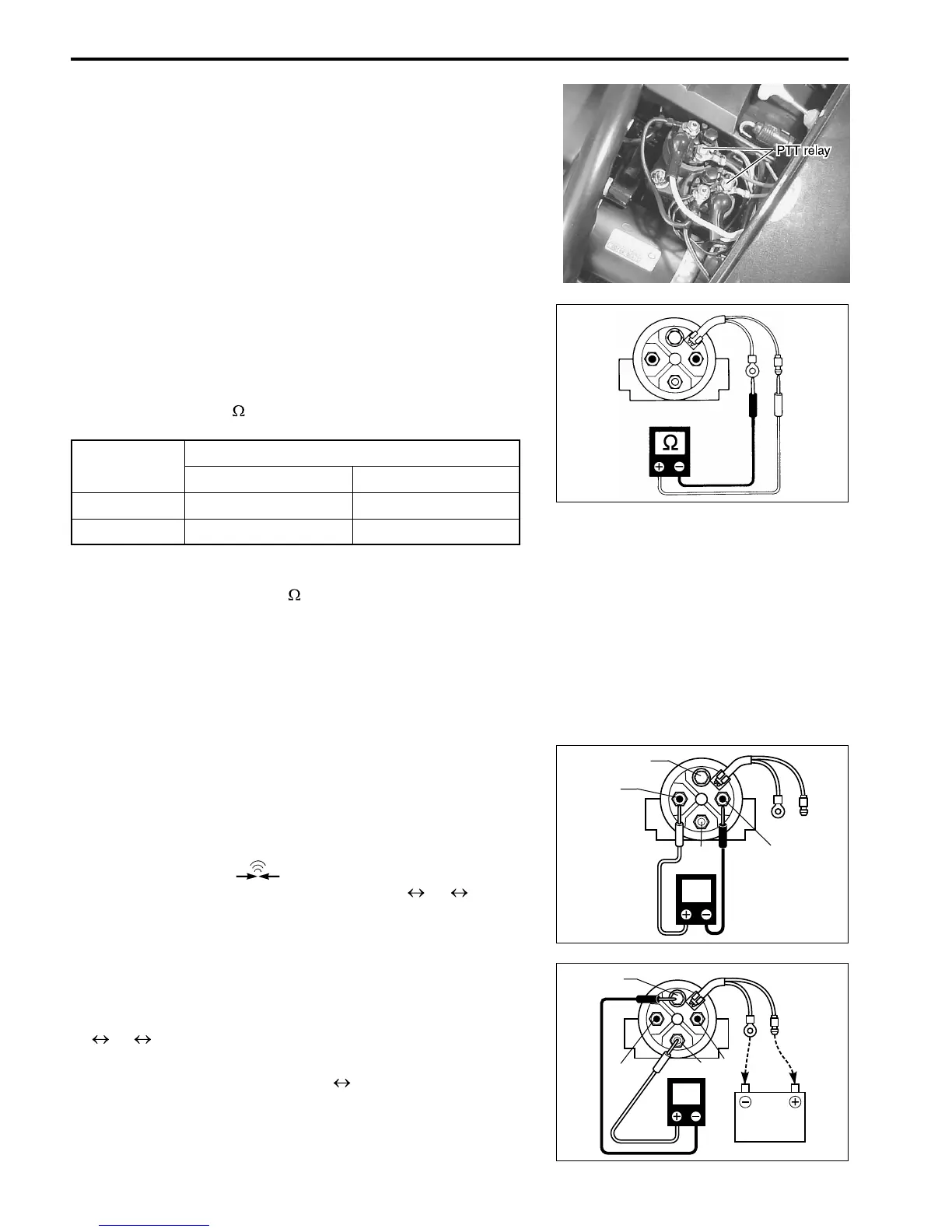
PTT MOTOR RELAY
Two methods can be used to test PTT relays.
Method 1.
Measure resistance between wiring leads of the relay.
09930-99320 : Digital tester
Tester range :
(Resistance)
Method 2.
Connect the wiring leads of the relay to battery (12V) and check
relay operation.
09930-99320 : Digital tester
Tester range : (Continuity)
When there is continuity between terminals 1 2 3, the
unit is considered to be without defect.
With Black lead wire connected to the battery negative (–) ter-
minal and Light blue or Pink lead wires are connected to bat-
tery positive (+) terminal there should be continuity between
2 3 4
..
..
.
With the lead wires are disconnected from the battery there
should be no continuity between 3 4.
The relay is considered to be without defect if continuity test
results are as stated above.
PTT relay solenoid coil resistance :
Standard 3.0 – 4.5
Tester probe connection
Red (+) Black (–)
UP Light Blue Black
DOWN Pink Black
[
U
[
S
B
Lbl(P)
Lbl(P)
CONT
1
2
3
4
CONT
Lbl(P)
B
12V BAT.
1
2
3
4
B

 Loading...


