3-14 ENGINE CONTROL
CAUTION LAMP
Check for illumination of the caution lamp.
[ 09930-89210 : 2 pin connector test cord
1. Disconnect lamp lead wires from engine harness.
2. Connect the test cord as shown.
3. For tests using 1.5V power source (or battery), connect the
lamp lead wire to the 1.5V power source (or battery) as shown
below.
Do not use Battery larger than 2V.
Pink lead wire Battery (+)
Black lead wire Battery (–)
When 1.5 V applied
Lamp ON
If out of specification, replace the caution lamp.
TESTING OIL PRESSURE CAUTION SYSTEM
To check the oil pressure caution circuit, follow the procedure
below.
NOTE:
Before checking the oil pressure caution circuit, make sure the
engine oil pressure is within specification.
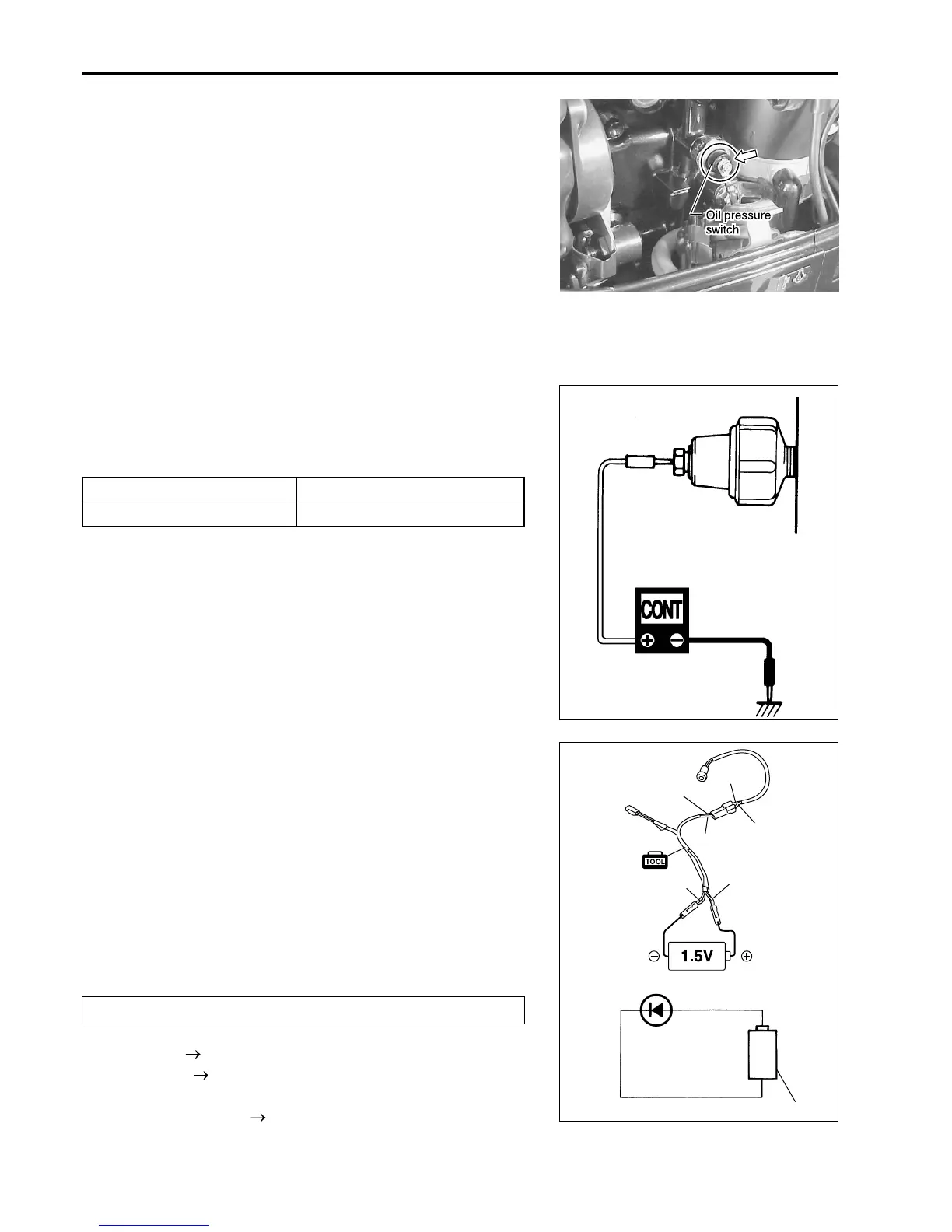
OIL PRESSURE SWITCH
1. Remove the blue/yellow lead wire from the oil pressure switch.
2. Check the continuity between the switch terminal and the en-
gine body ground.
[ 09930-99320 : Digital circuit tester
S Tester range :
??
??
? continuity
During engine running Infinity
At engine stop Continuity
If measurement exceeds specification, replace oil pressure
switch.
OIL LAMP CIRCUIT
1. Remove the blue/yellow lead wire from the oil pressure switch.
2. Start the engine.
3. Touch the blue/yellow lead wire to the engine body ground. If
the caution lamp comes on, the oil pressure switch circuit
and the oil pressure caution lamp are normal.
Pink
Black
1.5V Battery
P
P
B
B
B
P

 Loading...


