9-10 POWER TRIM AND TILT
INSTALLATION
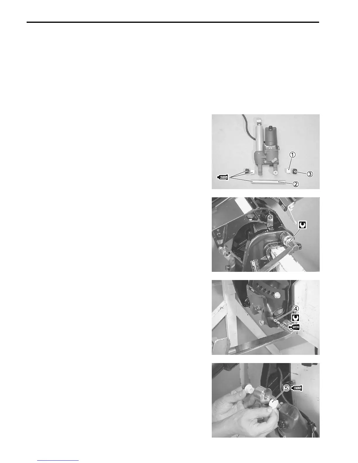
Installation is reverse order of removal with special attention to
the following steps.
Lower tilt rod full down position.
Apply Water Resistant Grease to the tilt cylinder lower shaft
and lower shaft bushes.
Install bushes 1, cylinder lower shaft 2 and lower collars 3 to
PTT unit.
99000-25160 : Water Resistant Grease
Place the PTT unit in position between the clamp brackets.
Tighten the clamp bracket shaft nut to specified torque.
Clamp bracket shaft nut :
43 N
.
m (4.3 kg-m, 31.0 lb.-ft.)
Tighten lower shaft bolts 4, pre-coated with thread lock, to speci-
fied torque.
II
II
I 99000-32050 : Thread Lock “1342”
!!
!!
! Cylinder lower shaft bolt : 23 N
.
m (2.3 kg-m, 16.5 lb.-ft)
Apply Water Resistant Grease to tilt rod upper bushes 5, then
install bushes in tilt rod.
Operate the PTT motor to extend the PTT rod upward.
Align the tilt rod with the hole in the swivel bracket as the tilt rod
extends.
99000-25160 : Water Resistant Grease
M
!
M

 Loading...


