8-4 MID UNIT
INSTALLATION
Installation is reverse order of removal with special attention to
the following:
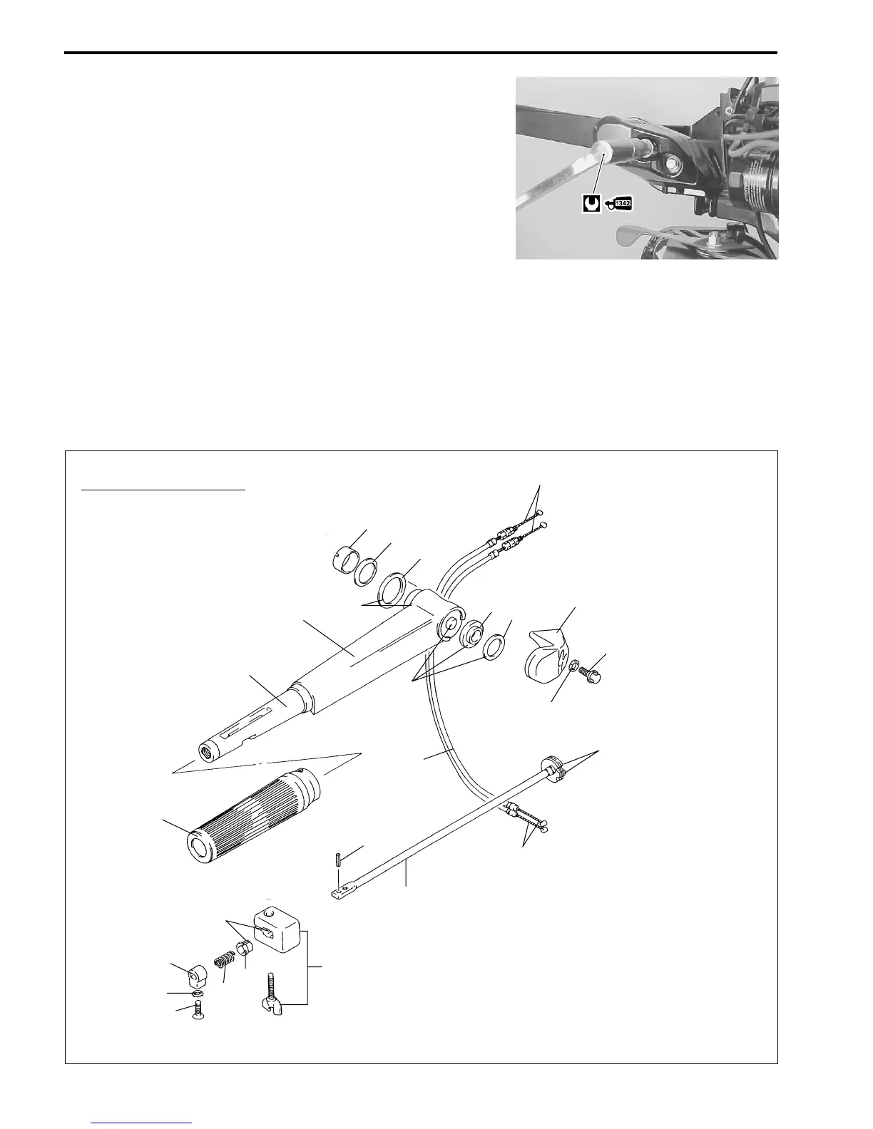
• Tiller handle cover
Install tiller handle and handle cover.
Tighten handle cover bolts, pre-coated with thread lock, to the
specified torque.
I 99000-32050 : Thread lock “1342”
[ Tiller handle bolt : 23 N
.
m (2.3 kg-m, 16.5 lb.-ft.)
• Installation of throttle cable (see page 5-13).
• Check shift linkage and lower unit gear engagement.
• Check wire and cable routing (see page 11-2 to 11-13).
Construction diagram
TILLER HANDLE DISASSEMBLY / ASSEMBLY
When disassembling or reassembling tiller handle, refer to the construction diagram below.
M
1
2
3
4
5
6
7
8
9
0
B
C
D
E
F
M
M
M
M
M
M
A
1 Tiller handle
2 Tiller handle cover
3 Bolt
4 Spacer
5 Shim
6 Washer
7 Handle grip
8 Handle rod
9 Pin
0 Adjuster
A Bush
B Spring
C Stopper
D Washer
E Screw
F Throttle cable
G Washer
H Wave washer
I Bush
G
H
I

 Loading...


