8-8 MID UNIT
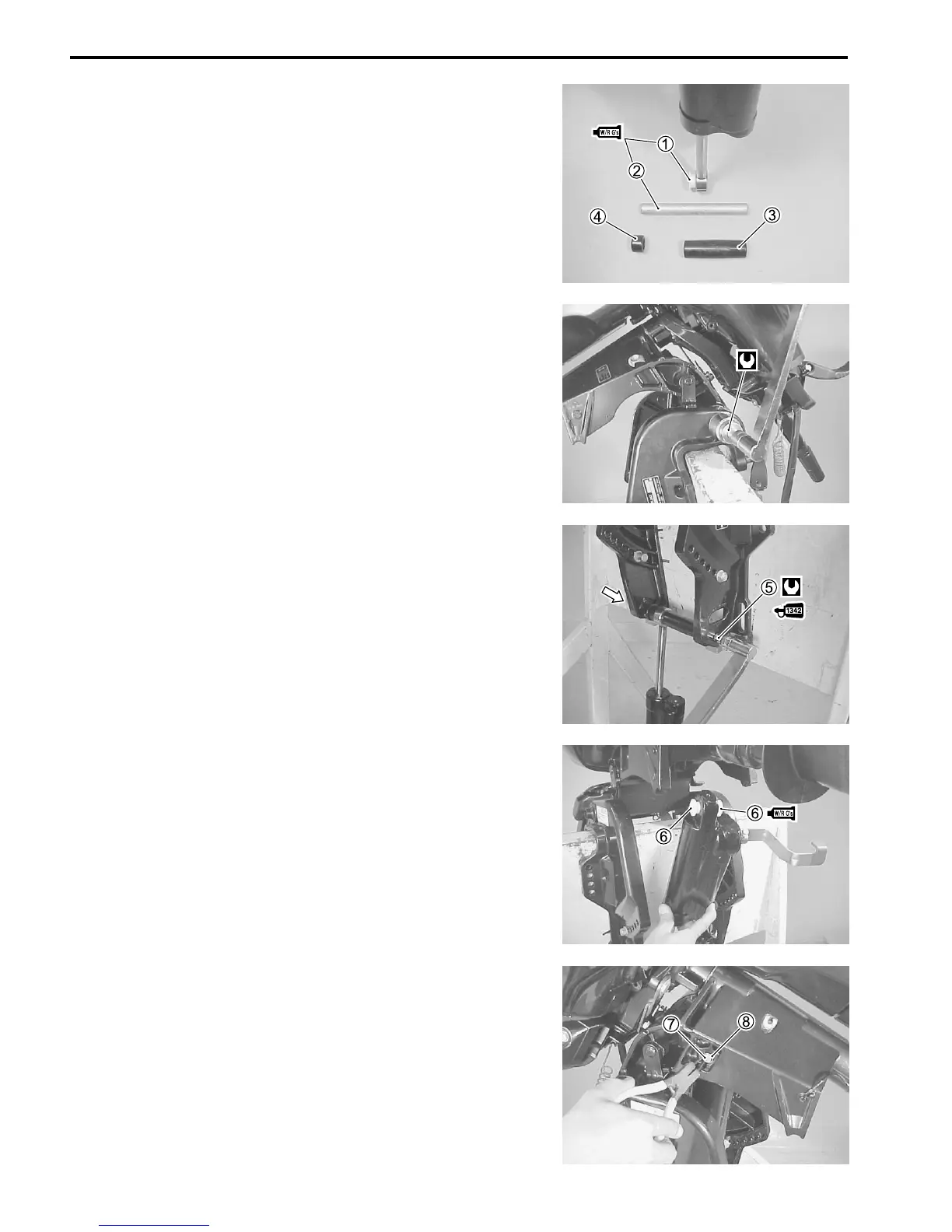
Gas assist tilt cylinder
Apply grease to each lower bush, cylinder lower shaft.
Install bushes 1, cylinder lower shaft 2, STBD lower collar 3,
PORT lower collar 4 to gas cylinder.
M
99000-25160 : Suzuki Water Resistant Grease
Place the gas cylinder in position between the clamp brackets.
Tighten clamp bracket shaft nut to specified torque.
! Clamp bracket shaft nut : 43 N
.
m (4.3 kg-m, 31.0 lb.-ft.)
Tighten lower shaft bolts 5, pre-coated with thread lock, to
specified torque.
I 99000-32050 : Thread lock “1342”
! Cylinder lower shaft bolt : 23 N
.
m (2.3 kg-m, 16.5 lb.-ft.)
Apply Water Resistant Grease to cylinder upper bush 6, then
install bush in cylinder upper eyelet.
M
99000-25160 : Water Resistant Grease
Align the cylinder upper eyelet with the hole in the swivel bracket.
Apply Water Resistant Grease to cylinder upper shaft 7, then
insert the upper shaft through the swivel bracket and gas cylin-
der.
Secure the upper shaft with the snap ring 8.
M 99000-25160 : Water Resistant Grease

 Loading...


