3-10 ENGINE CONTROL
CKP sensor
Tester probe connection
Red (+) Black (–)
No.1
No.2
Red Black
Red/White White/Black
CKP SENSOR
[[
[[
[ 09930-89240 : 4 pin connector test cord
RR
RR
R Peak voltmeter Stevens CD-77
Tester range : SEN 50
1. Disconnect CKP sensor lead wire connector from CDI unit.
2. Connect the test cord as shown.
3. Connect tester probe to sensor lead wires as shown.
4. Remove all spark plugs.
5. Crank with recoil starter or starter motor, then measure volt-
age.
CKP sensor output
Red – Black 3 V or over
Red/White – White/Black 3 V or over
If measurement exceeds specification, replace CKP sensor.
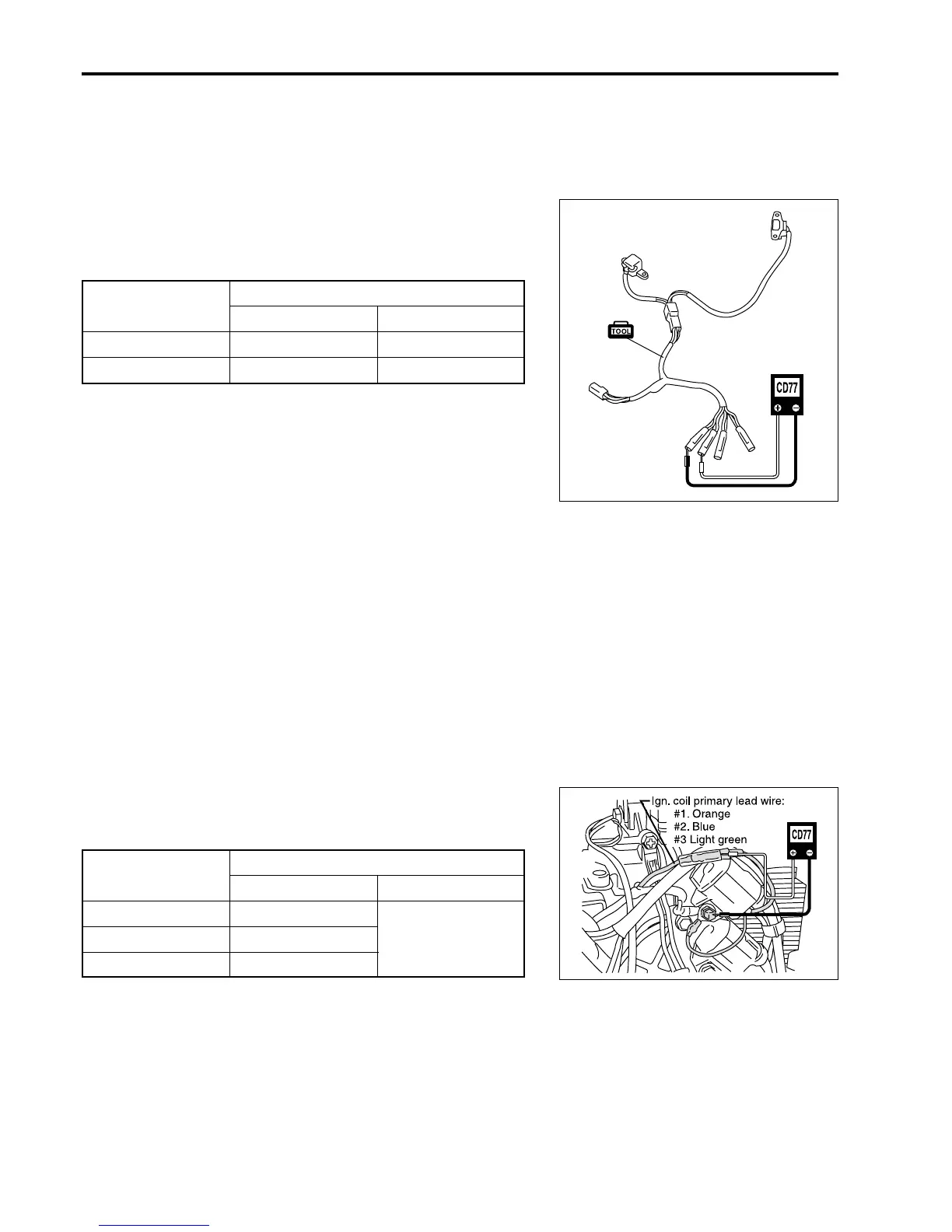
Ignition coil
Tester probe connection
Red (+) Black (–)
No.1
No.2
Black
(GND)
No.3
Orange
Blue
Light green
CDI UNIT
RR
RR
R Peak voltmeter Stevens CD-77
Tester range : POS 500
1. CDI unit must be connected to ignition coils.
2. Connect tester probe to ignition coil primary lead wires as
shown.
3. Remove all spark plugs.
4. Crank with recoil starter or starter motor, then measure volt-
age.
CDI unit output
Orange – Black 64 V or over
Blue – Black 64 V or over
Light green – Black 64 V or over

 Loading...


