6-1 POWER UNIT
INTAKE MANIFOLD ASSEMBLY
REMOVAL
Before removing intake manifold :
• Relieve fuel pressure. (See page 5-2)
• Disconnect battery cables from battery.
• Remove both side covers. (See page 7-1)
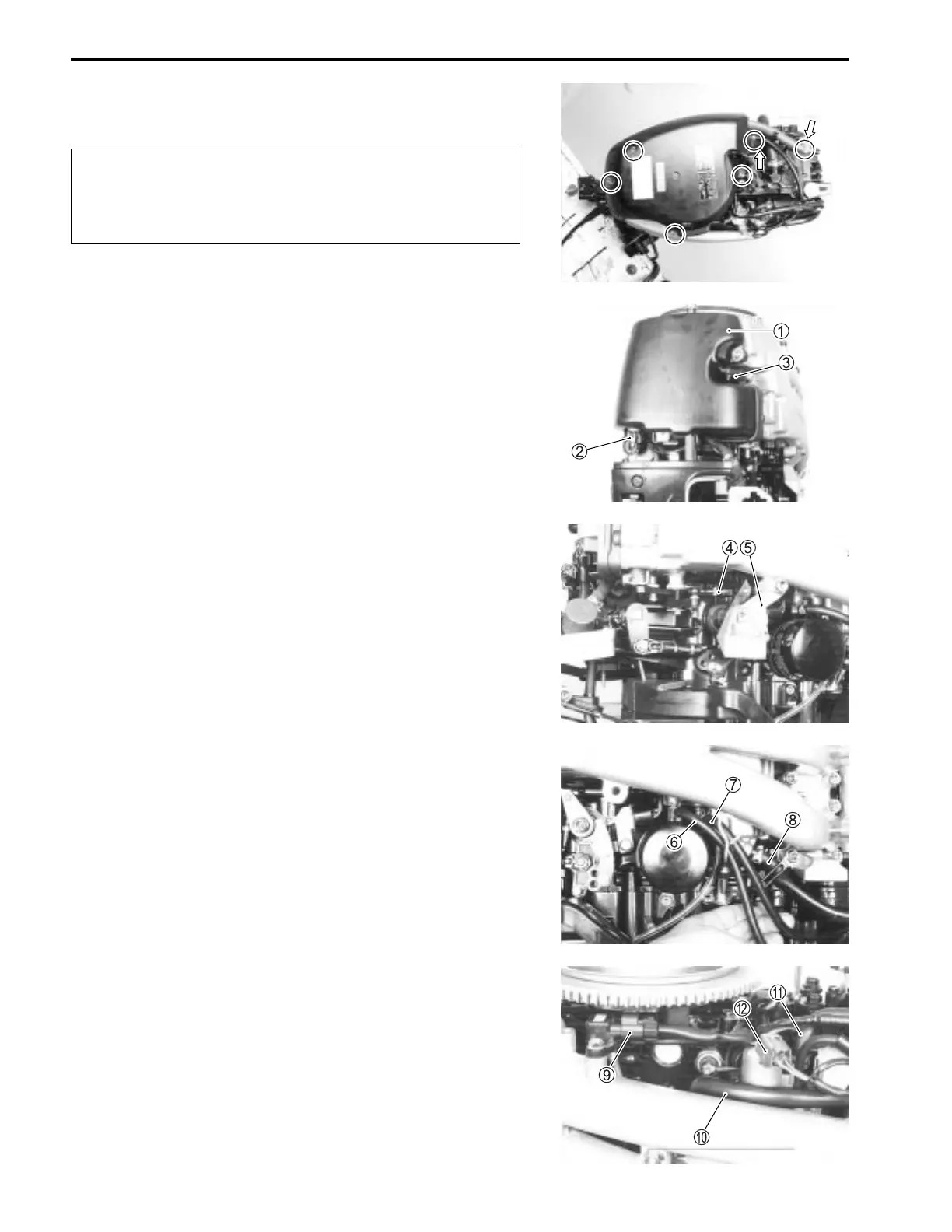
1. Remove flywheel cover and breather hose.
Remove evaporation hose from flywheel cover.
2. Remove silencer case
1 and disconnect lead wire connec-
tor
2 from IAT sensor.
3. Disconnect lead wire connector
3 from CTP switch.
4. Remove throttle rod
4 from throttle body.
5. Remove bolts and side cover holder
5.
6. Remove water inlet hose 6 and outlet hose 7 from vapor
separator.
7. Place a suitable container under the vapor separator, then
disconnect fuel return hose
8 from vapor separator.
8. Disconnect MAP sensor lead wire connector
9 at MAP sen-
sor.
Disconnect low pressure fuel inlet hose
0 from vapor sepa-
rator.
9. Disconnect high pressure fuel outlet hose
A from vapor
separator.
Disconnect high pressure fuel pump lead wire connector
B
at high pressure fuel pump.

 Loading...


