POWER UNIT 6-66
No.4 CRANKSHAFT
MAIN JOURNAL
No.3 CRANKSHAFT
MAIN JOURNAL
No.2 CRANKSHAFT
MAIN JOURNAL
No.1 CRANKSHAFT
MAIN JOURNAL
No.1 CYLINDER
WALL
No.2 CYLINDER
WALL
OIL PRESSURE
SWITCH
No.4 CAMSHAFT
HOUSING
No.1 CRANK PIN
No.2 CRANK PIN
No.1 PISTON
No.2 PISTON
No.3 CYLINDER
WALL
No.3 PISTON
No.3 CRANK PIN
OIL FILTER
OIL PUMP
PRESSURE
REGULATOR
OIL STRAINER
OIL PAN
No.1 CAMSHAFT
JOURNAL
(
IN
)
No.2 CAMSHAFT
JOURNAL
(
IN
)
No.3 CAMSHAFT
JOURNAL
(
IN
)
No.1 CAMSHAFT
JOURNAL
(
EX
)
No.2 CAMSHAFT
JOURNAL
(
EX
)
No.3 CAMSHAFT
JOURNAL
(
EX
)
No.1
CAM FACE
No.3
CAM FACE
No.2
CAM FACE
No.3
CAM FACE
No.1
CAM FACE
No.2
CAM FACE
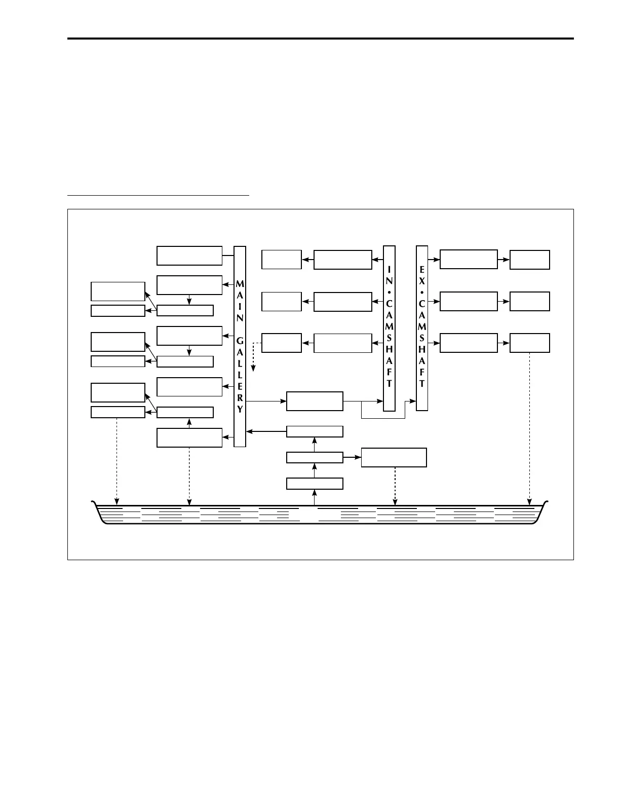
ENGINE LUBRICATION SYSTEM
A crankshaft driven trochoid type pump provides engine oil to all power unit components requiring lubrication.
Oil from the oil pan is drawn through the oil strainer and passed through a spin-on type oil filter before
entering the main oil gallery.
A pressure regulator (relief valve) is positioned between the oil pump and oil filter to maintain oil pressure at
a constant level.
From the main gallery, oil flow is directed through either drilled internal passages or by splash method to
those surfaces requiring lubrication.
ENGINE OIL LUBRICATION CHART

 Loading...


