3-13 ENGINE CONTROL SYSTEM
ELECTRONIC FUEL INJECTION SYSTEM
The fuel injection system used by the DF40/50 is a speed-density, multi-point, sequential, electronic fuel
injection type.
The fuel injection system is composed of the fuel line components, air intake components , and components
for system control (ECM,sensors, switches, etc.).
FUEL INJECTION CONTROL SYSTEM
OUTLINE
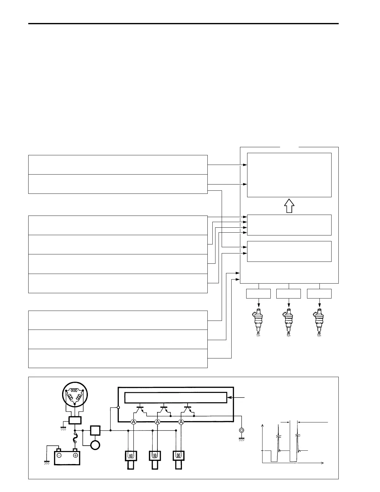
The sensors monitor current engine condition and send signals to the ECM. Based on these signals, the
ECM determines the optimum fuel injection time duration (fuel amount) and fuel injection timing (multi- point
sequential timing) and controls the injector operating signals accordingly.
Fuel injection timing is set at a constant compression stroke.
Basic sensors
Compensating sensors
Injector
MAP sensor :
Informs ECM of intake manifold pressure.
CKP sensor :
Informs ECM of engine speed and crankshaft angle.
Cylinder temperature sensor:
Informs ECM of cylinder temperature.
Fuel injection time duration
(amount) is determined by
a digital map designed in
relation to intake manifold
pressure and engine speed.
ECM
Fuel amount compensation
Others
CMP sensor:
Informs ECM of camshaft angle.
CTP switch:
Informs ECM of throttle position (open / closed).
IAT sensor:
Informs ECM of intake air temperature.
MAP sensor:
Informs ECM of barometric pressure at time of engine starting.
Battery voltage:
Multi-point sequential timing
Signal Signal Signal
Battery
charge
coil
Rectifier &
regulator
Battery
Ignition
switch
30A fuse
ECM
main
relay
ECM
CPU
Sensor/switch
signal input
Injector
A terminal voltage
(Time)
12V
(Voltage)
Injection time
duration
Neutral switch:
Informs ECM of shift position (neutral or nut).

 Loading...


