POWER UNIT 6-18
INSTALLATION
Installation is reverse of removal with special attention to fol-
lowing steps.
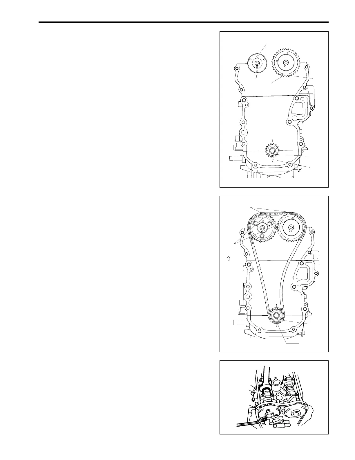
(1) Align crankshaft timing mark S with timing mark a on
crankcase as shown in figure by turning crankshaft.
(2) Install dowel pin 1 in intake camshaft.
Then turn the camshaft to position the dowel pin at the top,
as shown in figure.
Check that mark e on exhaust camshaft timing sprocket
aligns with timing mark b on cylinder head as shown in
figure.
(3) Install timing chain by aligning blue plate of timing chain
and arrow on exhaust camshaft timing sprocket as shown
in figure.
Install timing chain by aligning yellow plate of timing chain
and crankshaft timing mark S as shown in figure.
(4) Bring blue plate of timing chain into alignment with arrow
mark on intake camshaft timing sprocket, then install intake
cam timing sprocket to intake camshaft.
Tighten sprocket bolts to specified torque.
@@
@@
@ Camshaft timing sprocket bolt :
10 N
.
m (1.0 kg-m, 7.2 lb.-ft.)
1
b
e
S
a
NOTE:
Hold the camshaft by placing a wrench on the hexagon area of
the shaft.
Blue plate
Yellow plate
S
Arrow
mark
( )

 Loading...


