POWER UNIT 6-8
Install flywheel and tighten flywheel bolt to specified torque.
(See page 3-49)
09930-48720 : Flywheel holder
Flywheel bolt : 200 N
.
m (20.0 kg-m, 145 lb.-ft.)
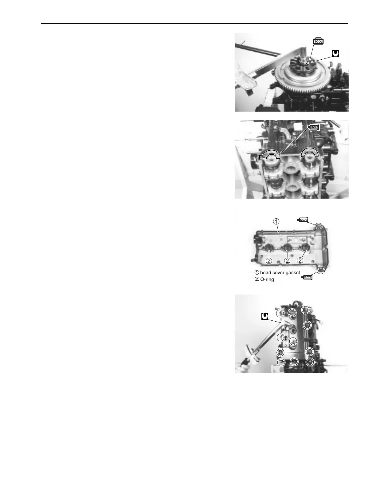
CYLINDER HEAD COVER
NOTE:
Before installing cylinder head cover, check tappet clearance.
(See page 2-8)
Apply Suzuki Bond to area as shown in figure.
99000-31140 : Suzuki Bond No. 1207B
Assemble new O-rings and cylinder head cover gasket to cylin-
der head cover.
NOTE:
Be sure to check all parts for wear or any damage before instal-
lation and replace any found defective.
Install cylinder head cover to cylinder head and tighten cover
bolts to specified torque.
Cylinder head cover bolt :
10 N
.
m (1.0kg-m, 7.2 lb.-ft.)
NOTE:
Use care when installing cylinder head cover.
Be certain cylinder head cover gasket and O-rings remain in
their correct position.
@
b
@
z

 Loading...


