Home
Suzuki
Motorcycle
DL650K5
Suzuki DL650K5 User Manual
4
of 1
of 1 rating
701 pages
Give review
Manual
Specs
To Next Page
To Next Page
To Previous Page
To Previous Page
Loading...
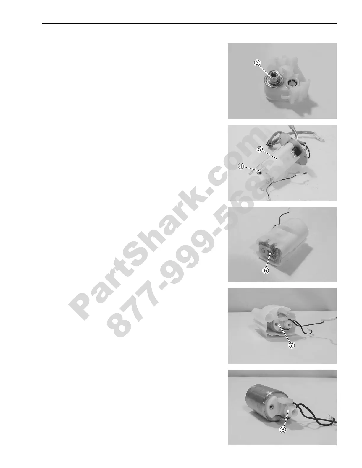
•
R
em
ove t
he fuel
press
ure r
egul
ator
3
.
•
R
em
ove t
he O-
ring
4
an
d fu
el pum
p h
older
5
.
•
R
em
ove t
he fuel
mes
h filter
6
.
•
R
em
ove t
he fuel
pump
7
.
•
R
em
ove t
he fuel
joint p
ipe
8
.
DL65
0K7/A
K7
(’07-M
OD
EL) 13-47
PartShark.com
877-999-5686
550
552
Table of Contents
General Information 1
11
Electrical System
1
Emission Control Information
1
General Information
1
Periodic Maintenance
1
Servicing Information
1
How to Use this Manual
4
Abbreviations Used in this Manual
6
Table of Contents
11
General Precautions
12
Warning/Caution/Note
12
Fuel, Oil and Engine Coolant Recommendation
14
Fuel (for Usa and Canada)
14
Fuel (for Other Countries)
14
Engine Oil (for Usa)
15
Engine Oil (for Other Countries)
15
Brake Fluid
15
Front Fork Oil
15
Engine Coolant
15
Water for Mixing
15
Anti-Freeze/Engine Coolant
16
Liquid Amount of Water/Engine Coolant
16
Serial Number Location
14
Suzuki Dl650K4 ('04-Model)
14
Break-In Procedures
16
Cylinder Identification
17
Information Labels
18
Specifications
19
Dimensions and Dry Mass
19
Engine
19
Drive Train
19
Chassis
20
Electrical
20
Capacities
20
Caster
20
Chassis
20
Country and Area Codes
21
Periodic Maintenance
23
Periodic Maintenance Schedule
24
Periodic Maintenance Chart
24
Lubrication Points
26
Maintenance and Tune-Up Procedures
27
Air Cleaner
27
Spark Plug
28
Valve Clearance
30
Fuel Line
35
Engine Oil and Oil Filter
35
Engine Idle Speed
37
Throttle Cable Play
37
Throttle Valve Synchronization
38
Evaporative Emission Control System (E-33 Only)
38
Pair (Air Supply) System
38
Clutch
39
Cooling System
40
Drive Chain
42
Brake
44
Tire
48
Steering
48
Front Fork
49
Rear Suspension
49
Exhaust Pipe Bolt
49
Chassis Bolt and Nut
50
Compression Pressure Check
52
Compression Test Procedure
52
Oil Pressure Check
53
Engine
55
Engine Components Removable with the Engine in Place
56
Engine Removal and Installation
57
Engine Removal
57
Engine Installation
65
Engine Disassembly
73
Engine Top Side
73
Engine Bottom Side
80
Engine Components Inspection and Servicing
90
Cylinder Head Cover
90
Camshaft/Camshaft Journal
91
Camshaft Runout
93
Cylinder Head
94
Cylinder
104
Piston and Piston Ring
105
Piston Ring Groove Width
106
Piston Ring Thickness
106
Conrod and Crankshaft
107
Crankcase
111
Crankshaft Journal Bearing
115
Crankcase Bearing and Oil Seal
120
Clutch
123
Primary Driven Gear Assembly
124
Gearshift Shaft/Gearshift Arm
125
Transmission
126
Starter Clutch
133
Generator and Signal Generator
134
Oil Pump
135
Clutch Release
135
Engine Reassembly
136
Engine Bottom Side
136
Engine Top Side
148
Fi System Diagnosis
164
Precautions in Servicing
166
Electrical Parts
166
Fuse
167
Ecm/Various Sensors
167
Electrical Circuit Inspection Procedure
169
Using Testers
172
Fi System Technical Features
173
Injection Time (Injection Volume)
173
Compensation of Injection Time (Volume)
174
Injection Stop Control
174
Fi System Parts Location
175
Fi System Wiring Diagram
177
Self-Diagnosis Function
178
User Mode
178
Dealer Mode
179
Tps Adjustment
180
Fail-Safe Function
181
Fi System Troubleshooting
182
Customer Complaint Analysis
182
Self-Diagnostic Procedures
184
Self-Diagnosis Reset Procedure
184
Malfunction Code and Defective Condition
185
C12" Ckp Sensor Circuit Malfunction
187
C13" Iap Sensor Circuit Malfunction
189
C14" Tp Sensor Circuit Malfunction
192
C15" Ect Sensor Circuit Malfunction
195
C21" Iat Sensor Circuit Malfunction
197
C23" to Sensor Circuit Malfunction
199
C24" or "C25" IGNITION SYSTEM MALFUNCTION
200
C28" Stv Actuator Circuit Malfunction
201
C29" Stp Sensor Circuit Malfunction
202
C31" Gear Position (Gp) Switch Circuit Malfunction
205
C32" or "C33" FUEL INJECTOR CIRCUIT MALFUNCTION
206
C41" Fp Relay Circuit Malfunction
208
C42" Ig Switch Circuit Malfunction
208
C49" Pair Control Solenoid Valve Circuit Malfunction
209
C44" Ho2 Sensor (Ho2S) Circuit Malfunction (E-02, 19)
211
Ckp Sensor Inspection
213
Ckp Sensor Removal and Installation
213
Ect Sensor Inspection
213
Ect Sensor Removal and Installation
213
Iap Sensor Inspection
213
Iap Sensor Removal and Installation
213
Sensors
213
Tp Sensor Inspection
213
Tp Sensor Removal and Installation
213
Tps Adjustment
213
Ho2 Sensor Inspection (E-02, 19)
214
Ho2 Sensor Removal and Installation
214
Iat Sensor Inspection
214
Iat Sensor Removal and Installation
214
Stp Sensor Adjustment
214
Stp Sensor Inspection
214
Stp Sensor Removal and Installation
214
To Sensor Inspection
214
To Sensor Removal and Installation
214
Fuel System and Throttle Body
215
Fuel System
216
Fuel Delivery System
216
Fuel Pump
217
Fuel Pressure Regulator
219
Fuel Injector
219
Fuel Pump Control System
220
Fuel System
221
Fuel Tank Lift-Up
221
Fuel Tank Removal
221
Fuel Tank Installation
221
Fuel Pressure Inspection
222
Fuel Pump Inspection
223
Fuel Pump Relay Inspection
224
Fuel Pump and Fuel Filter Removal
224
Fuel Mesh Filter Inspection and Cleaning
226
Fuel Pump and Fuel Mesh Filter Installation
226
Throttle Body and Stv Actuator
228
Construction
228
Air Cleaner and Throttle Body Removal
229
Throttle Body Disassembly
232
Throttle Body Cleaning
236
Throttle Body Inspection
236
Throttle Body Reassembly
237
Stv Synchronization
241
Throttle Body Installation
241
Stp Sensor Adjustment
242
Air Cleaner Box Installation
242
Tp Sensor Adjustment
243
Fast Idle Inspection
244
Fast Idle Adjustment
245
Throttle Valve Synchronization
246
Cooling and Lubrication Systemcooling and Lubrication System
250
Engine Coolant
252
Cooling Circuit
253
Cooling Circuit Inspection
253
Radiator
254
Removal
254
Inspection and Cleaning
256
Installation
256
Radiator Cap
257
Inspection
257
Water Hose
257
Cooling Fan
258
Inspection
258
Removal
258
Installation
258
Cooling Fan Thermo-Switch
259
Removal
259
Inspection
259
Installation
259
Ect Sensor
260
Removal
260
Inspection
260
Installation
261
Thermostat Case Assembly
262
Removal
262
Inspection
262
Installation
263
Water Pump
264
Removal and Disassembly
264
Inspection
266
Reassembly and Installation
267
Lubrication System
270
Oil Pressure
270
Oil Filter
270
Oil Pressure Regulator
270
Oil Strainer
270
Oil Jet
270
Oil Pump
270
Oil Pressure Switch
270
Oil Cooler
271
Removal
271
Inspection and Cleaning
271
Installation
272
Engine Lubrication Flow Chart
273
Oil Pan
273
Chassis
276
Electrical System
363
Engine Lubrication Circuit
274
Exterior Parts
278
Construction
278
Removal
280
Installation
284
Front Wheel
285
Construction
285
Removal
286
Inspection and Disassembly
286
Reassembly and Remounting
288
Front Fork
292
Construction
292
Removal and Disassembly
293
Inspection
296
Reassembly and Remounting
297
Suspension Setting
301
Steering and Handlebar
302
Construction
302
Removal
303
Inspection and Disassembly
306
Reassembly and Remounting
307
Steering Tension Adjustment
310
Rear Wheel
311
Construction
311
Removal
312
Inspection and Disassembly
313
Reassembly and Remounting
316
Rear Shock Absorber
320
Construction
320
Removal
321
Inspection
322
Rear Shock Absorber Disposal
322
Remounting
323
Suspension Setting
324
Rear Swingarm
325
Construction
325
Removal
326
Inspection and Disassembly
327
Reassembly
330
Remounting
332
Final Inspection and Adjustment
333
Front Brake
334
Construction
334
Brake Pad Replacement
335
Brake Fluid Replacement
336
Caliper Removal and Disassembly
337
Caliper Inspection
338
Caliper Reassembly and Remounting
339
Brake Disc Inspection
341
Master Cylinder Removal and Disassembly
341
Master Cylinder Inspection
342
Master Cylinder Reassembly and Remounting
343
Rear Brake
344
Construction
344
Brake Pad Replacement
345
Brake Fluid Replacement
347
Caliper Removal and Disassembly
347
Caliper Inspection
349
Brake Disc Inspection
350
Caliper Reassembly and Remounting
350
Service Limit
350
Master Cylinder Removal and Disassembly
351
Master Cylinder Inspection
353
Master Cylinder Reassembly and Remounting
353
Tire and Wheel
355
Tire Removal
355
Inspection
355
Valve Installation
356
Tire Installation
357
Tire Pressure
358
Drive Chain
359
Drive Chain Cutting
359
Drive Chain Connecting
360
Cautions in Servicing
364
Connector
364
Coupler
364
Clamp
364
Fuse
364
Semi-Conductor Equipped Part
365
Battery
365
Connecting the Battery
365
Wiring Procedure
365
Using the Multi Circuit Tester
366
Location of Electrical Components
367
Charging System
369
Trouble Shooting
369
Main Fuse
369
Inspection
371
Starter System and Side-Stand/Ignition Interlock System
374
Trouble Shooting
374
Starter Motor Removal and Disassembly
376
Starter Motor Inspection
377
Starter Motor Reassembly
378
Starter Relay Inspection
381
Side-Stand/Ignition Interlock System Parts Inspection
382
Ignition System
385
Troubleshooting
385
Inspection
387
Combination Meter
391
Removal and Disassembly
391
Inspection
392
Indicators
394
Lamps
398
Headlight, Brake Light/Taillight and Turn Signal Light
398
Headlight
398
Turn Signal Light
398
Relays
399
Turn Signal/Side-Stand Relay
399
Starter Relay
399
Fuel Pump Relay
399
Switches
400
Inspection
401
Battery
402
Specifications
402
Initial Charging
402
Servicing
404
Recharging Operation
404
Electrical
369
Servicing Information
405
Troubleshooting
406
Malfunction Code and Defective Condition
406
Engine
408
Radiator (Cooling System)
414
Chassis
415
Brakes
416
Electrical
417
Battery
419
Wire Harness, Cable and Hose Routing
420
Wire Harness Routing
420
Heated Oxygen Sensor (Ho2S) Wire Routing (for E-02, 19)
422
Engine Electrical Parts Set-Up
423
Speed Sensor Lead Wire Routing
424
Throttle Cable Routing
425
Clutch Cable Routing
426
Throttle Body Installation/Hose Routing
427
Cooling System Hose Routing
428
Front Brake Hose Routing
430
Rear Brake Hose Routing
431
Fuel Tank Drain Hose Routing
432
Fuel Tank Installation
433
Pair (Air Supply) System Hose Routing
434
Seat Lock Cable Routing
435
Head Lamp Set-Up
435
Absorber Hose Routing
436
Battery Cushion Installation
436
Side-Stand Set-Up
437
Brake Pedal/Footrest Set-Up
437
Engine Cap Installation
438
Footrest Set-Up
439
Handlebar Balancer Installation
439
Special Tools
440
Tightening Torque
444
Engine
444
Fi System Parts
445
Chassis
446
Tightening Torque Chart
447
Service Data
448
High Beam Indicator Light
456
Neutral Indicator Light
456
Speedometer Light
456
Turn Signal Indicator Light
456
Emission Control Information
461
Emission Control Systems
462
Fuel Injection System
462
Crankcase Emission Control System
463
Exhaust Emission Control System (Pair System)
464
Noise Emission Control System
465
EVAPORATIVE EMISSION CONTROL SYSTEM (Only for E-33)
465
Pair (Air Supply) System Inspection
466
Hoses
466
Pair Reed Valve
466
Pair Control Solenoid Valve
467
Pair (Air Supply) System Hose Routing
468
Heated Oxygen Sensor (Ho2S) Wire Routing (E-02, 19)
468
EVAPORATIVE EMISSION CONTROL SYSTEM INSPECTION (Only for E-33)
470
Hoses
470
Only for E
470
Evap Canister
470
Fuel-Shut off Valve
470
EVAP CANISTER HOSE ROUTING (Only for E-33)
471
Specifications
474
Clutch
494
3 Rd
495
4 Th
495
Drive Chain
495
Top
495
Battery
498
Electrical
498
Headlight
498
Spark Plug
498
High Beam Indicator Light
499
License Plate Light
499
Neutral Indicator Light
499
Position/Parking Light
499
Speedometer Light
499
Turn Signal Indicator Light
499
Turn Signal Light
499
Dl650K7/Ak7 ('07-Model)
505
Oil Pressure/Coolant Temperature/Fuel Injection Indicator Light
512
Chassis
514
Periodic Maintenance Schedule
515
Periodic Maintenance Chart
515
Maintenance and Tune-Up Procedures
516
Spark Plug
516
Throttle Cable Play
518
Throttle Valve Synchronization
518
Fi System Diagnosis
519
Ecm Terminal
519
Fail-Safe Function
520
Dtc Table and Defective Condition
521
Dtc Troubleshooting
524
For E
544
Fuel Discharge Amount Inspection
548
Fuel Pump
548
Fuel Pump Removal and Disassembly
550
Throttle Body
554
Air Cleaner Box and Throttle Body Installation
562
Throttle Valve Synchronization
565
Isc Valve
567
Isc Valve Pre-Set
568
Ignition System
569
Inspection
569
Combination Meter
571
Fuel Level Gauge Inspection
571
Fuel Level Meter Inspection
571
INTRODUCTION of ABS (for DL650A)
572
ABS Indicator Light
575
Cautions in Servicing
576
Abs Components
579
Abs Components Location
579
Abs Coupler Connection Diagram
580
Abs Wiring Diagram
581
Abs Unit System Diagram
582
Abs Troubleshooting
583
Troubleshooting Procedure
584
DTC (Diagnostic Trouble Code) OUTPUT
593
Dtc Deleting and Abs Operation Check
595
Sds Check
597
Use of Sds Diagnostic Procedures
598
Use of Sds Diagnosis Reset Procedure
599
Dtc Table of Abs
605
Dtc Troubleshooting
606
Abs Component Removal, Inspection and Installation
623
Wire Harness, Hose Routing and Sensor Installation
632
Battery Protector Installation
644
Special Tools
645
Tightening Torque
645
Service Data (Dl650K7)
646
Headlight
653
High Beam Indicator Light
654
License Plate Light
654
Neutral Indicator Light
654
Position/Parking Light
654
Speedometer Light
654
Turn Signal Indicator Light
654
Turn Signal Light
654
Service Data (Dl650Ak7)
658
ABS Indicator Light
666
4
Based on 1 rating
Ask a question
Give review
Questions and Answers:
Need help?
Do you have a question about the Suzuki DL650K5 and is the answer not in the manual?
Ask a question
Suzuki DL650K5 Specifications
General
Brand
Suzuki
Model
DL650K5
Category
Motorcycle
Language
English
Related product manuals
Suzuki DL650
82 pages
Suzuki DL650A
139 pages
Suzuki V-Storm DL650A
127 pages
Suzuki V Storm DL650A K9
127 pages
Suzuki V-Strom DL650 2017
161 pages
Suzuki DL650/AK7DL650/AK8
701 pages
Suzuki DL1000
444 pages
Suzuki DL 650 2004
467 pages
Suzuki DL1000A 2018
161 pages
Suzuki DR650SE
277 pages
Suzuki DR200SE
262 pages
Suzuki drz 400E
334 pages