TM8100/TM8200 Service Manual Frequency Synthesizer Fault Finding 179
© Tait Electronics Limited June 2006
9 Frequency Synthesizer Fault Finding
Introduction This section covers the diagnosis of faults in the frequency synthesizer.
The sections are divided into the following:
■ Initial checks
■ Fault diagnosis of RF PLL circuitry
■ Fault diagnosis of FCL circuitry.
The initial checks will indicate whether it is the RF PLL or the FCL that is
suspect. Note that the synthesizer is a closed-loop control system. A fault in
one area can cause symptoms to appear elsewhere. Locating the fault can
therefore be difficult.
Measurement
Tech ni que s
The radio must be in CCTM for all the fault-diagnosis procedures of this
section. The CCTM commands required are listed in Table 9.1. Full details
of the commands are given in “Computer-Controlled Test Mode
(CCTM)” on page 118. Use an oscilloscope with a x10 probe for all voltage
measurements required. The signals should appear stable and clean.
Consider any noise or unidentified oscillations as evidence of a fault
requiring investigation. Use a frequency counter for all measurements of
high frequencies. The RF power output from the frequency synthesizer will
not exceed 10mW. If a probe is used for frequency measurements, use the
x1 setting.
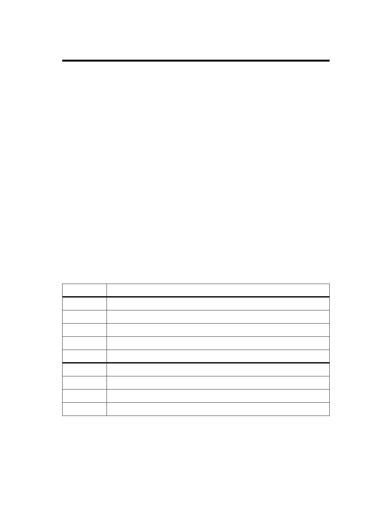
Table 9.1 CCTM commands required for the diagnosis of faults in the frequency synthesizer
Command Description
72 Read lock status of RF PLL, FCL and LO2 — displays xyz (0=not in lock, 1=in lock)
101 x y 0 Set transmit frequency (x in hertz) and receive frequency (y in hertz) to specified values
205 Reset calibration parameters to their default values
301 0 10 Calibrate VCXO of FCL
302 0 10 Calibrate VCO(s) of RF PLL
334 x Set synthesizer on (x=1) or off (x=0) via DIG SYN EN line
335 x Set transmit-receive switch on (x=1) or off (x=0) via DIG SYN TR SW line
389 x Set synthesizer mode to slow (x=0) or fast (x=1)
393 1 x Write data x to FPGA
 Loading...


