TM8100/TM8200 Service Manual TMAA04-04 Crossband Linking Cable 545
© Tait Electronics Limited June 2006
27.3 Operational Testing
1. On the receiving radio, inject an on-channel RF signal at a level of
-70dBm, modulated to ±3kHz deviation (wide bandwidth channel)
or ±1.5kHz (narrow bandwidth channel), at 1kHz AF.
2. On the transmitting radio, the resulting deviation should be:
■ ±3kHz (with a tolerance of ±200Hz) on a 25kHz wide
bandwidth channel.
■ ±1.5kHz (with a tolerance of ±200Hz) on a 12.5kHz narrow
bandwidth channel.
27.4 Interface Specification
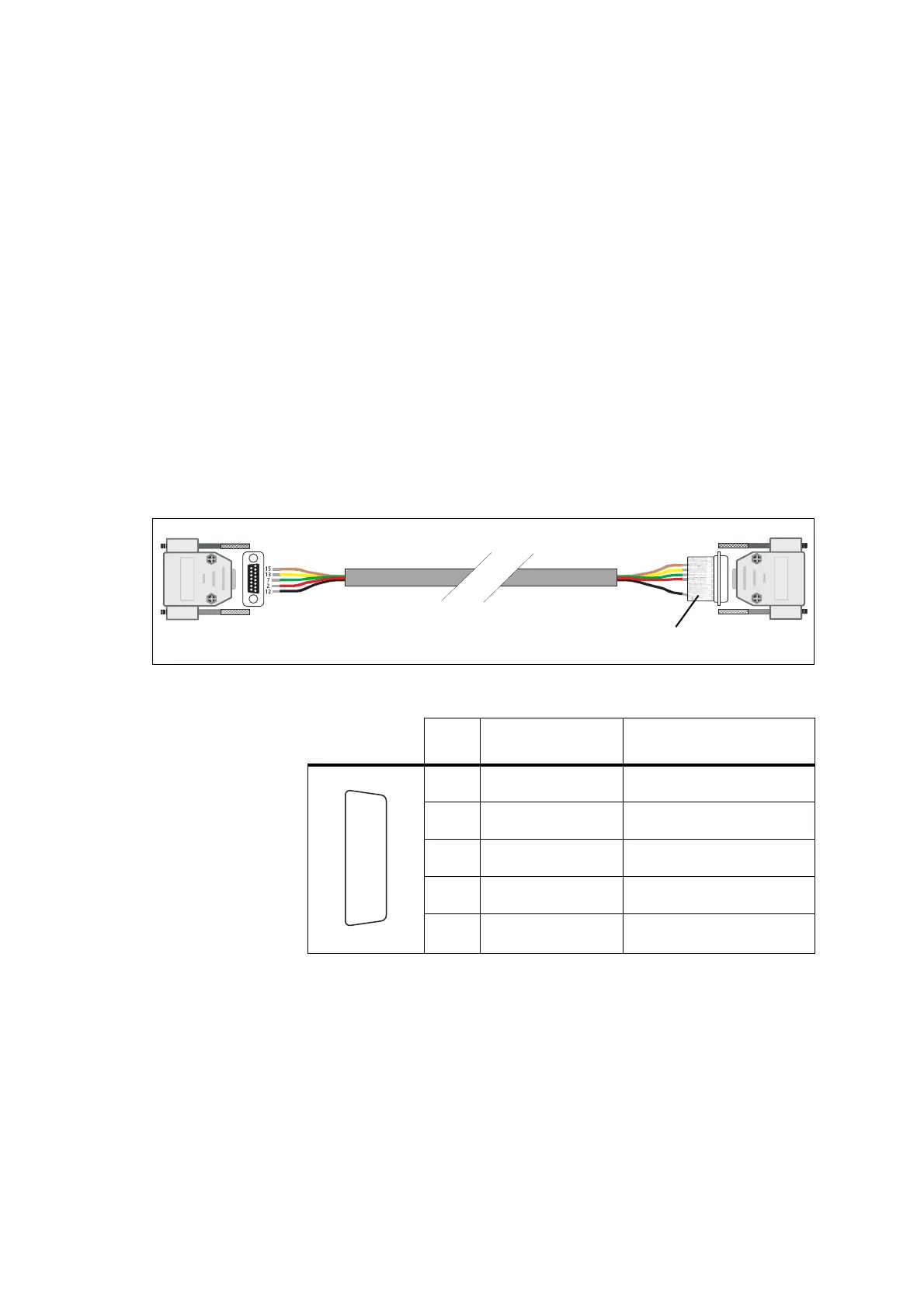
The following table and diagram summarizes the signals used for the crossband
linking cable on the radios’ auxiliary connectors and shows the interface
between the cable and the radios.
Figure 27.1 TMAA04-04 crossband linking cable
auxiliary connector
radio 1
auxiliary connector
radio 2
crossband linking board
Table 27.7 Auxiliary connectors—pins and signals
Pin Signal name Description
2 AUX_GPIO5
busy (output)
7 AUD_TAP_IN
audio tap input
12 AUX_GPI1
PTT (input)
13 AUD_TAP_OUT
audio tap output
15 AGND
analogue ground
J
B
C
D
E
F
G
H
I
1)
1!
1@
1#
1$
1%
rear view
 Loading...


