TM8100/TM8200 Service Manual Frequency Synthesizer Fault Finding 217
© Tait Electronics Limited June 2006
9.7 VCO and Related Circuitry (VHF Radios)
Introduction If there is no fault with the power supplies, the PLL inputs and output, and
the loop filter, check the VCO and related circuitry. The procedures in this
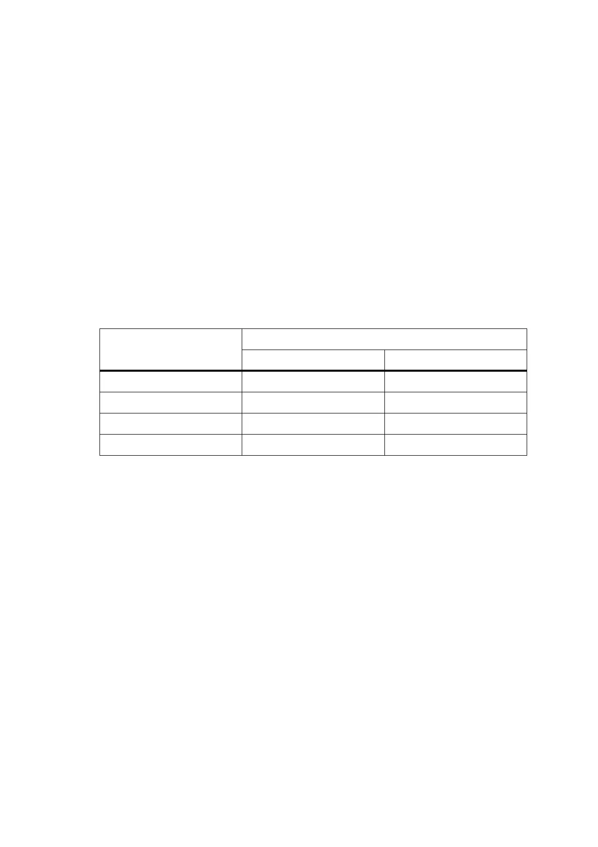
section apply only to VHF radios; the VHF frequency bands are defined in
Table 9.5. There are six aspects:
■ Task 28: check VCO
■ Task 29: repair PLL feedback
■ Task 30: repair VCO
■ Task 31: check transmit-receive switch
■ Task 32: repair switching network
■ Task 33: check buffer amplifier.
The measurement points for diagnosing faults in the VCO and related
circuitry are summarized in Figure 9.12.
Table 9.5 Minimum and maximum frequencies for the different VHF frequency bands
Frequency band Frequency in MHz
Minimum Maximum
A4 55 ± 5125 ± 5
B1 84 ± 5200 ± 5
C0 137 ± 5247 ± 5
D1 167 ± 5287 ± 5
 Loading...


