460 TMAA01-01 Line-Interface Board TM8100/TM8200 Service Manual
© Tait Electronics Limited June 2006
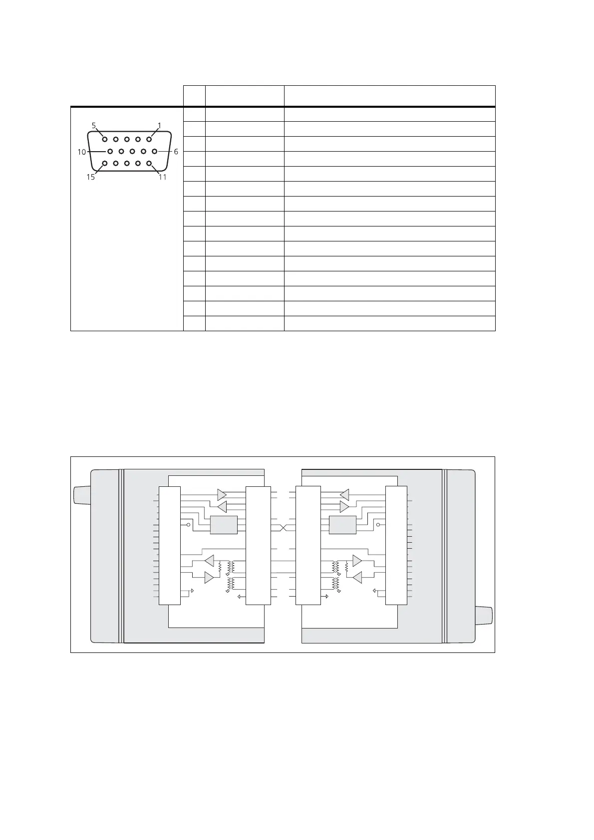
17.6 Line-Interface Board Application
The following diagram shows the control of two radios operated together,
crossband or repeater linked.
Table 17.8 External options connector (SK1) — pins and signals
Pin Signal Description
1 KEYING signal line keying
2 RS-422
serial data TX-
11 RS-422/RS-232
serial data TX+/RS-232 TXD
3 PTT-IN bi-directional keying input
4 4W_LINE_IN - 4-wire line in negative
10 4W_LINE_IN +
4-wire line in positive
5 RS-422/RS-232 serial data RX+/RS-232 RXD
6 RS-422 serial data RX-
7GND
ground
8 — not connected
9 13V8 FROM RADIO switched 13.8V supply from the radio
12 BUSY/GATE busy or receiver gate output. 5V CMOS logic level.
13 — not connected
14 4W_LINE_OUT - 4-wire line out negative or 2-wire line in/out negative
15 4W_LINE_OUT + 4-wire line out positive or 2-wire line in/out positive
front view
Figure 17.3 Two radios connected as a repeater/crossband link
keying
logic
SK2
TXD
AUD_TAP_OUT
AGND
DGND
PTT FROM OPT
RXD
13V8
—
—
—
—
AUD_TAP_IN
BUSY
2° BUSY
AUX
GPIO5
—
—
KEYING
PTT_IN
BUSY/GATE
LINE IN+
LINE IN-
LINE OUT+
LINE OUT-
AGND
13V8_SW
11
2
1
3
12
9
4
5
6
SK1
15
14
10
11
2
1
3
12
9
4
5
6
15
14
10
keying
logic
KEYING
PTT_IN
BUSY/GATE
RS-422/RS-232 TX
RS-422 TX
LINE IN+
LINE IN-
LINE OUT+
LINE OUT-
AGND
13V8_SW
11
11
22
11
33
1212
99
1010
44
1515
1414
5
6
5
6
SK1SK2
external
options
connector
external
options
connector
internal
options
connector
internal
options
connector
line-interface board line-interface board
18
18
17
17
9
9
10
15
12
12
11
11
6
6
7
10
4
13
5
11
2
2
14
8
7
10
4
13
5
14
8
1616
3
18
17
9
10
12
11
6
1
2
16
3
18
17
9
15
12
11
6
2
16
3
3
TXD
IOP_TXD
AUD_TAP_OUTAUD_TAP_OUT
AUX_MIC_AUD
AGND
AGND
DGND
DGND
PTT FROM OPT
IOP_GPIO1
RX_AUD
RXD
IOP_RXD
RX_BEEP_IN
13V8
—
—
—
—
13V8_SW
AUD_TAP_INAUD_TAP_IN
RSSI
IOP_GPIO2
BUSY
2° BUSY
IOP_GPIO3
AUX
IOP_GPIO4
IOP_GPIO5
GPIO5
IOP_GPIO6
IOP_GPIO7
1
IOP_TXD
AUD_TAP_OUT
AUX_MIC_AUD
AGND
DGND
IOP_GPIO1
RX_AUD
IOP_RXD
RX_BEEP_IN
13V8_SW
AUD_TAP_IN
RSSI
IOP_GPIO2
IOP_GPIO3
IOP_GPIO4
IOP_GPIO5
IOP_GPIO6
IOP_GPIO7
—
—
5
6
RS-422/RS-232 RX
RS-422 RX
RS-422/RS-232 TX
RS-422 TX
RS-422/RS-232 RX
RS-422 RX
5
6
 Loading...


