426 Fault Finding of Control Head with Graphical Display TM8100/TM8200 Service Manual
© Tait Electronics Limited June 2006
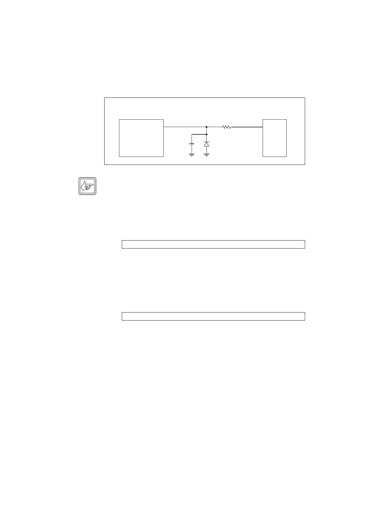
14.12 PTT Faulty
The PTT signal from the microphone connector is connected to the FPGA
via a resistor (R25) and relayed to the radio as a digital command.
Note This section only describes faults to the PTT caused by the con-
trol head, which has been established during the initial servicing
tasks by means of elimination test.
If the PTT is faulty:
1. With no PTT switch and hookswitch operated, check whether pin 4
of J106 is 4V.
If the signal is correct, continue with Step 2.
If the signal is incorrect, inspect R25 for open or shorted contacts.
Repair if necessary. Repeat Step 1.
2. With the PTT switch operated, check whether the same 4V are
pulled to ground on the other side of R25.
If the signal is correct, continue with Step 3.
If the signal is incorrect, inspect D106 and C108 for short-circuits.
Repair if necessary.
3. Verify continuity between R25 and the FPGA. Repair PCB track if
possible.
Figure 14.17 Circuit diagram of the PTT circuitry
J106 pin 4: 4V
R25: GND
J106
Microphone
Connector
FPGA
4
FP PTT
R25
MIC PTT
C108
D106
 Loading...


