C
Ref. DCD01/3067 - UC500_en_D
12/27
CCommunication
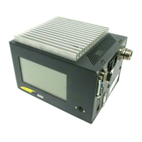
1. RS232 cable
Metallic SubD9F for shielded cables
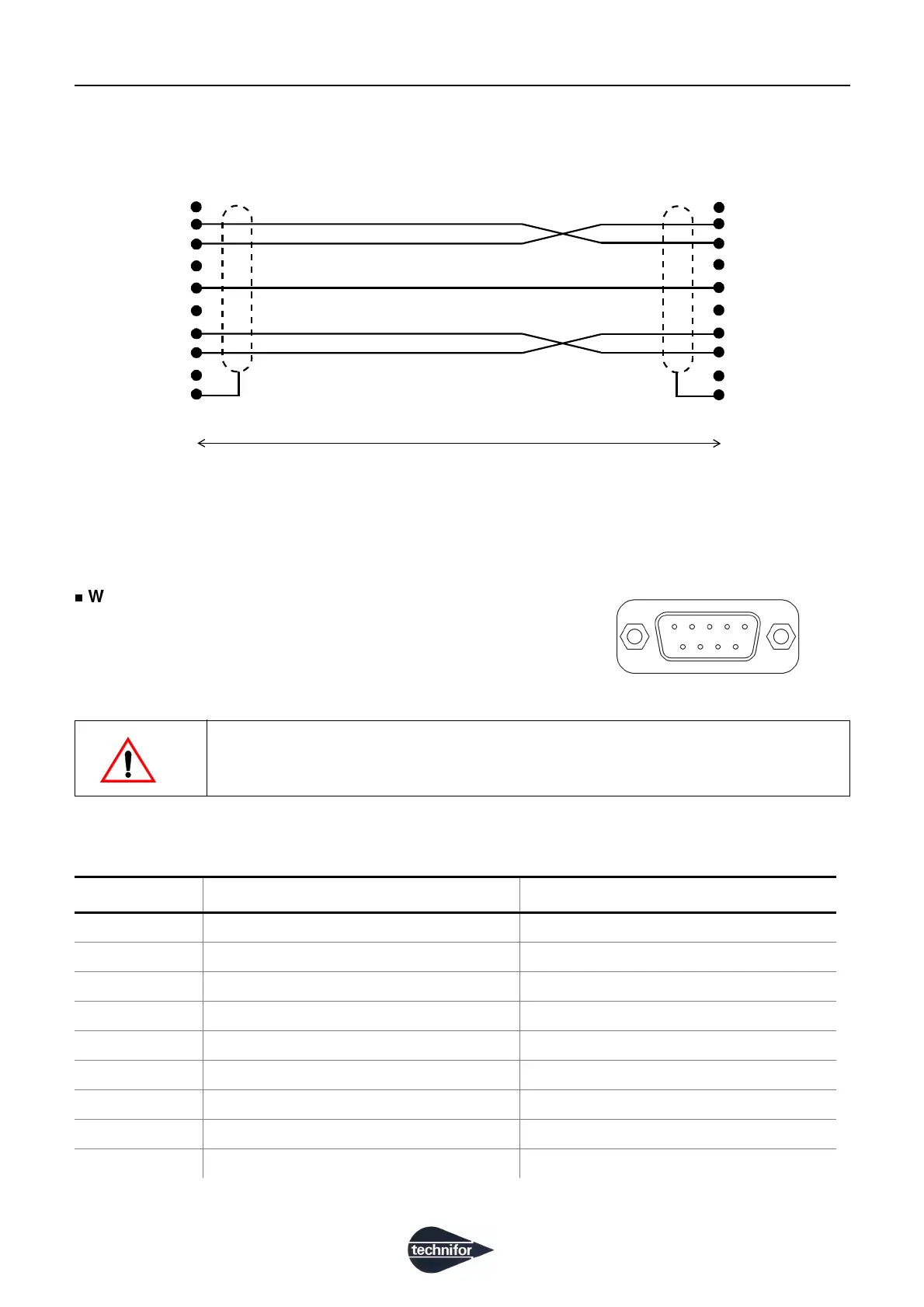
2. Dedicated Inputs/Outputs
Wiring of the female 9 SubD connector
This connector allows to communicate with the machine. It contains
dedicated All-or-Nothing Inputs and Outputs. They are used in the
marking cycle.
Pin functions
Use exclusively shielded cable. Connect the shielding to the electrical ground on
either side of the cable.
Number Description Allocation
1 Internal power supply + 24 V - 300 mA max.
2 Relay # 2 Output - Fault
3 Relay # 3 Output - Marking in progress
4 Input 1 Input - Start marking
5 Gnd Grounding
6 Relay # 1 Output - Machine ready
7 Common Relay # 1-2
8 Relay # 3 Output - Marking in progress
9 Input 2 Input - Stop marking
2 m (6.56 ft)
Sub. D9F Sub. D9F
1
2
3
4
5
6
7
8
9
1
2
3
4
5
6
7
8
9
RD
TD
OV
RTS
CTS
Grounding
Grounding
51
96
 Loading...