ADescription of the Control Unit
B
Ref. DCD01/3067 - UC500_en_D
9/27
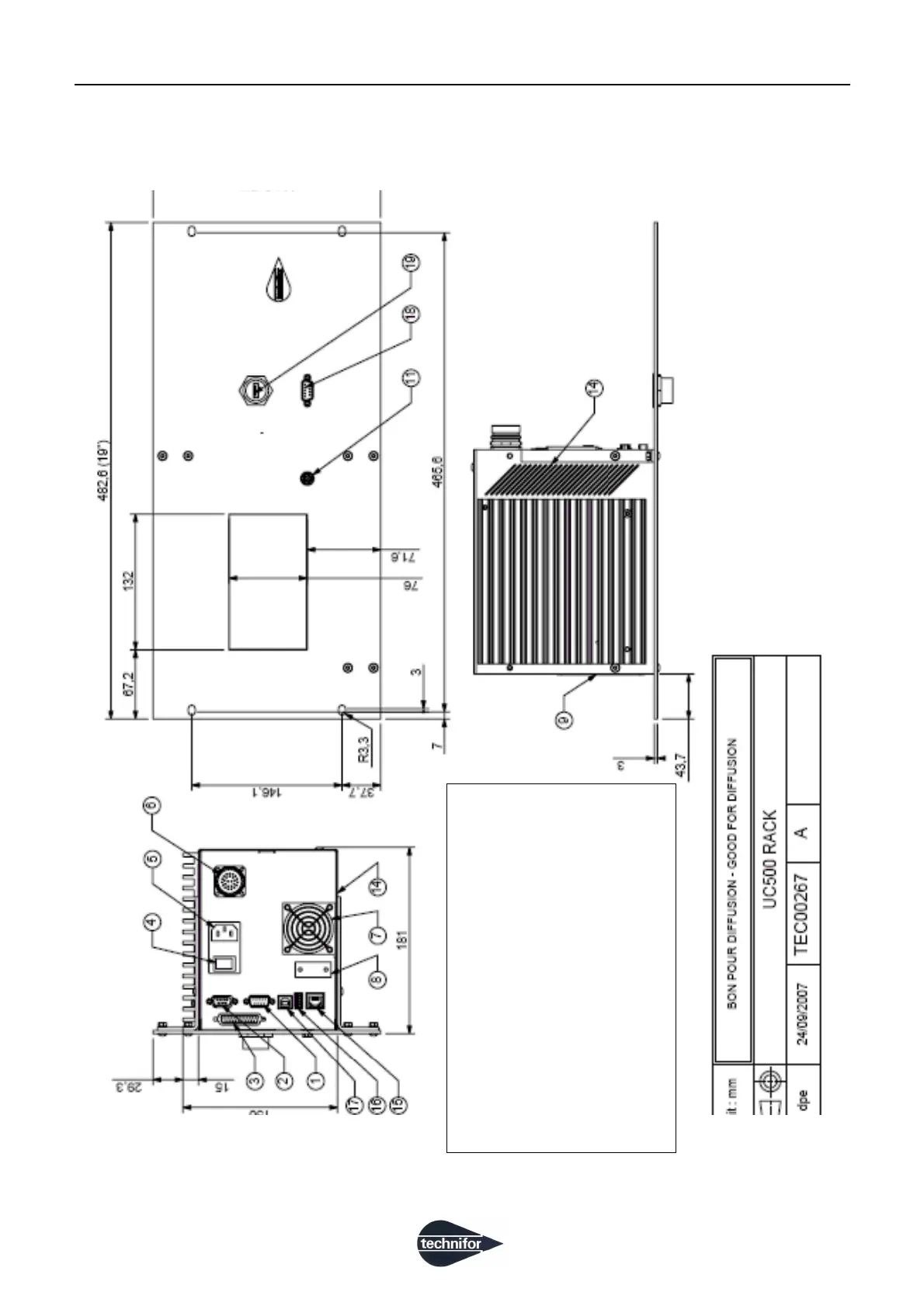
5. Dimensional drawings of the Control Unit in rack configuration
1: SubD 9M: RS232 link
2: SubD 9F: dedicated Inputs/Outputs
3: SubD 25F: generic Inputs/Outputs
4: On/Off + fuse carrier
5: Power supply input: 90/253 V AC - 50/60 Hz
6: Connections to the marking head
7: Ventilator (electromagnetic version only)
8: Circular marking device option
9: EC plate
10: Two mounting plates (delivered unassembled)
11: MiniDin 6 point(s): PS2 keyboard
14: Air vent (DO NOT OBSTRUCT)
15: RJ45: Ethernet connection
16: USB A
17: USB B
18: SubD 9M: RS232 link
19: USB A
 Loading...