D
Ref. DCD01/3067 - UC500_en_D
22/27
DInstallation
1. Connections
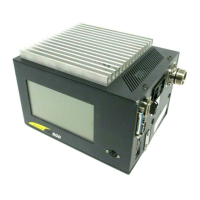
To use the CCU, 4 connections must be performed, in the following order:
• female SubD 9 with reset jumpers
• keyboard
• marking head
• power supply: 90 - 253 V AC - 50/60 Hz
2. Wiring of the "Stop marking" contact
The machine comes delivered with a SubD 9 point connector with bridge so that it can be used immediately.
It must be connected to the dedicated Inputs/Outputs connector located on the right side of the CCU.
The connector supplied is only used to test the machine. Under normal operating conditions, open the electrical
connection between pins 5 and 9 to activate the "Stop marking" function. If this connection is not performed, the
Stop function is active and no marking is possible.
3. Keyboard connection
Connect the connecting plug to the female DIN connector located on the CCU’s front panel.
The keyboard allows to use the internal marking program T05.
If the CCU is placed on a table or a workbench, imperatively mount the feet before the
power up.
The feet provide clearance for the air passages under the CCU.
The different elements of the equipment must be connected with the power off. The power supply should
be connected last.
 Loading...